
Description
Hard-Numbers: Technical Specifications
- Rated Voltage: 12/24 VDC
- Output Voltage Range: 12 to 24 VDC (+20%, -15%)
- Output Current: 0.5A maximum per point; 2A maximum per common terminal
- Inrush Current: 4.78A for 10ms
- On Response Time: 2ms maximum
- Off Response Time: 2ms maximum
- Off-State Leakage: 1mA maximum
- Output Voltage Drop: 1V maximum
- Isolation (Field to Backplane): 250VAC continuous; 1500VAC for 1 minute (optical)
- Isolation (Group to Group): 250VAC continuous; 1500VAC for 1 minute
- Backplane Power Draw: 110mA @ 5VDC (all outputs energized)
- Operating Temperature: 0°C to +60°C (+32°F to +140°F)
- Weight: 0.69 lbs (0.31 kg)
- Hot-Swap Support: Yes (RX3i Universal Backplane only)
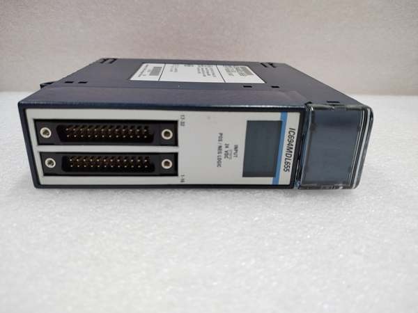
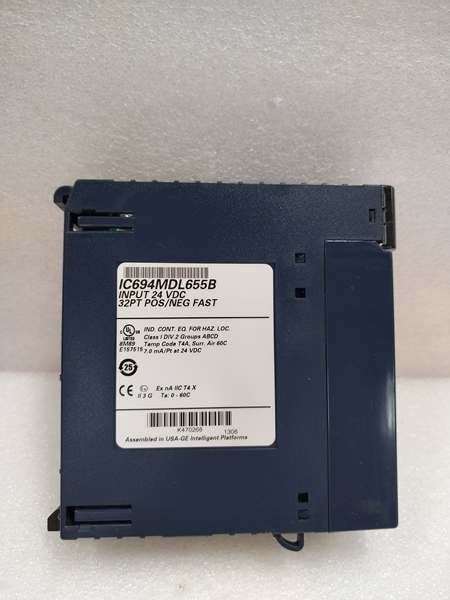
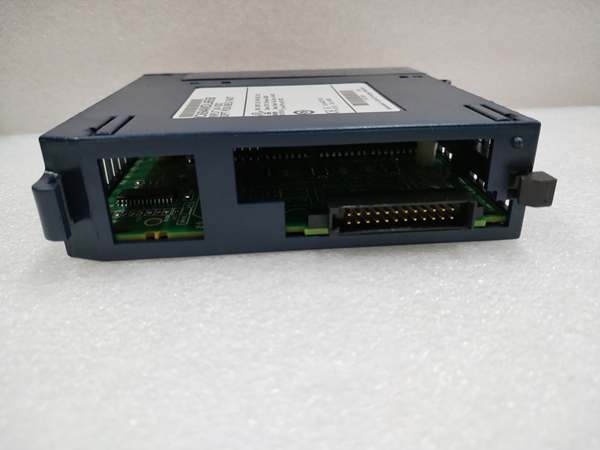
GE IC694MDL655
The Real-World Problem It Solves
You’ve got a cabinet full of 24VDC field devices—solenoid valves, contactors, stack lights—and you need to switch them from your PLC without burning through rack space. This module stuffs 16 outputs into a single slot with enough current handling for most small inductive loads, plus isolation between groups so you can run separate power domains.
Where you’ll typically find it:
- Packaging lines driving pneumatic solenoid manifolds (8-12 valves per section)
- Motor control centers tripping small contactors and starter interlocks
- Process skids with indicator towers and alarm beacons
Bottom line: One card replaces two 8-point modules, freeing up slots for analog I/O or comms cards in space-constrained panels.
Hardware Architecture & Under-the-Hood Logic
This module has no onboard microprocessor—it’s a dumb MOSFET switch array controlled directly by the CPU through the backplane. All the intelligence lives in the rack processor; this card just executes the on/off commands. Optical isolators separate the field wiring from the 5V backplane logic, protecting the CPU from ground loops and transient spikes.
Signal flow from command to load:
- CPU writes output state to %Q memory address mapped to this module’s slot position.
- Backplane bus transmits the 16-bit output word to the module’s input latches.
- Optical isolators receive the logic signals and convert them to isolated gate drive signals for the MOSFETs.
- MOSFET drivers switch the output terminals—each MOSFET acts as a solid-state switch between the DC+ bus and the output terminal.
- Current flows from DC+ terminal, through the MOSFET, out the output terminal, through the load, and returns via the common terminal to the negative power bus.
The two groups share no electrical connection inside the module—you can power Group 1 from one 24V supply and Group 2 from a completely separate supply without creating a ground loop.
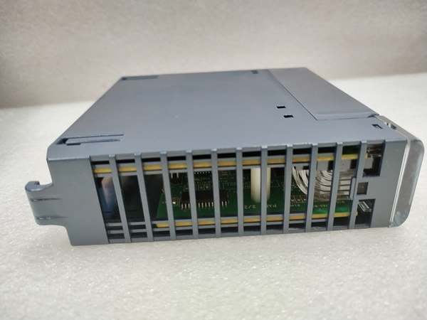
GE IC694MDL655
Field Service Pitfalls: What Rookies Get Wrong
Wiring the Load on the Wrong Side of the Output Terminal
Positive logic means this module sources current—it pushes current out of the output terminal toward the load. Rookies wire one side of the load to DC+ and the other to the output terminal, then scratch their heads when nothing switches. The current has nowhere to go because the MOSFET is on the high side, not the low side.
Field Rule: Load connects between the output terminal and DC common (negative bus). Current flows OUT of the output terminal, through the load, to the return.
Ignoring the Per-Common Current Limit
Eight outputs at 0.5A each equals 4A total—twice the 2A per-common rating. The module doesn’t have internal fuses, so nothing pops immediately. Instead, the common terminal trace overheats over time, solder joints fatigue, and you get intermittent failures months later in a hot cabinet.
Quick Fix: Calculate your worst-case simultaneous load per group. If you’re driving eight 24VDC solenoids at 0.4A each, split them across both groups or add an interposing relay card.
Assuming Built-In Fuses for Fault Protection
There are no fuses on this module. None. A dead-short on an output channel will weld the MOSFET in the ON state, and your load stays energized until you kill the external supply. This design philosophy assumes you’re providing your own branch circuit protection per NEC and local codes.
Field Rule: Fuse each group’s DC+ feed at the power supply. Size for 125% of your maximum expected load, or match it to your wire ampacity—whichever is lower.
Overlooking Off-State Leakage with Sensitive Loads
1mA off-state leakage is nothing when you’re driving a 10W solenoid coil. But if you’re feeding a solid-state relay input or a high-impedance analog circuit, that leakage can keep the downstream device in an undefined state. The module never truly “opens”—it just leaks less when off.
Quick Fix: Add a 10kΩ bleed resistor across sensitive load inputs to shunt leakage current to a known state. For SSR inputs, check the minimum trigger current spec against the 1mA leakage.
Commercial Availability & Pricing Note
Please note: The listed price is for reference only and is not binding. Final pricing and terms are subject to negotiation based on current market conditions and availability.


