
Description
Hard-Numbers: Technical Specifications
| Parameter | Specification |
|---|---|
| Number of Inputs | 32 (four isolated groups of 8 inputs each) |
| Input Voltage Range | 0 to 30 VDC |
| Rated Voltage | 24 VDC |
| Supply Voltage Range | 20 to 30 VDC |
| On-State Voltage | 11.5 to 30 VDC |
| Off-State Voltage | 0 to 5 VDC |
| Input Current | 7.0 mA per point (typical at rated voltage) |
| On-State Current | 3.2 mA minimum |
| Off-State Current | 1.1 mA maximum |
| Input Filter Times | 0.5ms, 1.0ms, 2.0ms, 5ms, 10ms, 50ms, and 100ms (selectable per module) |
| On Response Time | 0.5ms, 1.0ms, 2.0ms, 5.0ms, 10.0ms, 50.0ms, and 100.0ms (as per filter setting) |
| Off Response Time | 0.5ms, 1.0ms, 2.0ms, 5.0ms, 10.0ms, 50.0ms, and 100.0ms (as per filter setting) |
| Isolation (Field to Backplane) | 250 VAC continuous; 1500 VAC for 1 minute (optical) |
| Isolation (Group to Group) | 250 VAC continuous; 1500 VAC for 1 minute |
| Power Consumption | 300 mA (all inputs on) from 5V bus on backplane |
| Maximum Inrush Current | 4.78 A for 10 ms |
| Module ID | 0x058h |
| Diagnostics | Terminal block presence reported to RX3i CPU |
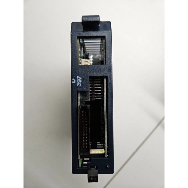
| Terminal Blocks Required | Box-style (IC694TBB032) or Spring-style (IC694TBS032) – sold separately |
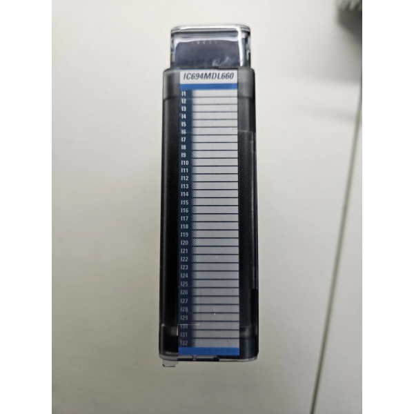
| LED Indicators | 32 green LEDs (input status), 1 red/green TB LED (terminal block status) |
| Weight | 0.365 kg (0.80 lbs) |
| Dimensions | 14.00 x 3.50 x 14.00 cm (5.51 x 1.38 x 5.51 inches) |
| CPU Compatibility | RX3i CPU release 2.90 or later |
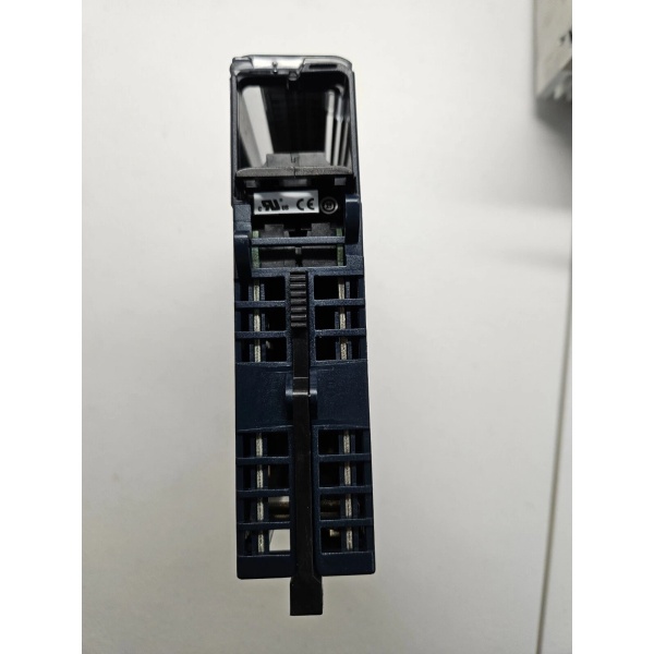
| Approvals | UL 508, CSA C22.2 No. 142-M1987, Class I Div. 2 Groups A, B, C, D (hazardous locations) |
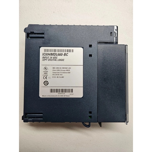
IC694MDL660
The Real-World Problem It Solves
This module provides high-density digital input capability with flexible positive/negative logic support and configurable filter times, eliminating the need for multiple lower-density modules while accommodating various sensor types and environments. Its group isolation prevents ground loops, and selectable filter times eliminate false signals from mechanical bounce or electrical noise.
Where you’ll typically find it:
- Automotive assembly lines monitoring limit switches and proximity sensors
- Packaging machinery tracking photoelectric sensors and push button stations
- Material handling systems detecting position sensors and safety interlocks
- Process control plants monitoring selector switches and status indicators
Bottom line: It’s your high-density solution for 24VDC digital signal acquisition with flexible configuration for diverse field device types and industrial environments.
Hardware Architecture & Under-the-Hood Logic
The IC694MDL660 contains 32 independent input circuits organized in four isolated groups of eight inputs each, with individual LED indicators and configurable digital filters. Each group shares a common connection point, with optical isolation between field wiring and the PLC backplane. The module uses 48 input bits and 16 output bits to exchange point status and filter information with the RX3i CPU.
Signal flow breakdown:
- Field device (sensor/switch) applies 24VDC signal to input terminal
- Input signal passes through protection circuitry (voltage clamping, current limiting)
- Configurable digital filter (0.5ms to 100ms) debounces input transitions
- Filtered signal evaluated against on/off voltage thresholds (11.5VDC on, 5VDC off)
- Opto-coupler provides isolation between field side and logic side
- Isolated signal feeds to input detection circuitry
- Digital state stored in module’s dual-port memory
- PLC CPU reads input state from dual-port memory during scan cycle
- LED drivers activate corresponding green status indicators (one per input)
- Terminal block presence detector reports TB status to CPU
- Red/green TB LED indicates terminal block locked (green) or not locked (red)
- Module status and filter settings communicated to CPU via 16 output bits
Group organization:
- Group 1: Inputs 1-8, Common terminal 9
- Group 2: Inputs 9-16, Common terminal 18
- Group 3: Inputs 17-24, Common terminal 27
- Group 4: Inputs 25-32, Common terminal 36
Data exchange with CPU:
- 48 input bits: Point status (32 bits) + diagnostic information
- 16 output bits: Filter configuration and module control

IC694MDL660
Field Service Pitfalls: What Rookies Get Wrong
Positive vs Negative Logic ConfusionEngineers wire sensors for positive logic but configure PLC program expecting negative logic (or vice versa), causing all inputs to appear inverted.
- Field Rule: Verify sensor output type (PNP = positive logic, NPN = negative logic). Match wiring to sensor type: Positive logic = sensor source connects to +24V, negative logic = sensor source connects to ground. Test with known-good input before commissioning.
Inadequate Filter Time SelectionTechnicians use 0.5ms filter time on vibrating machinery with mechanical limit switches, causing false trigger counts and erratic PLC behavior.
- Field Rule: Select filter time based on application: 0.5-1ms for high-speed counters, 2-5ms for general machinery, 10-50ms for vibrating environments, 100ms for slow manual switches. Increase filter time if experiencing false triggers.
Mixing Groups Without IsolationInstallers connect inputs from different groups to the same common reference, defeating group isolation and creating ground loop paths.
- Field Rule: Each group (8 inputs) must have its own isolated common connection. Never share commons between groups when noise immunity is critical. Use separate isolated power supplies for each group if using common-based sensors.
Terminal Block Not LockedNew techs overlook the TB LED status indicator, operating with terminal block not properly locked, causing intermittent connections under vibration.
- Field Rule: Verify TB LED is GREEN after installation. RED LED = terminal block not locked. Push terminal block firmly until it clicks and TB LED turns green. Re-check after any maintenance.
Ignoring CPU CompatibilityTeams install IC694MDL660 with Series 90-30 PLC CPUs instead of RX3i, causing communication failures and module recognition issues.
- Field Rule: This module requires RX3i CPU release 2.90 or later. Incompatible with Series 90-30 PLC CPUs. Verify CPU model and firmware version before installation. Use IC693MDL655 for Series 90-30 applications.
Exceeding Voltage RangeEngineers apply 32VDC or higher to inputs, potentially damaging input circuitry despite the 30VDC maximum rating.
- Field Rule: Ensure input voltage never exceeds 30VDC. Verify power supply regulation and account for voltage spikes. Use surge protectors or transient voltage suppressors on long cable runs from noisy environments.
Poor Common Wiring PracticeTechnicians wire multiple sensors with different ground references to the same group common, creating ground potential differences and erratic input behavior.
- Field Rule: Group all sensors sharing the same ground reference together on the same group. For sensors with different grounds, use different groups or isolate with signal conditioners. Maintain ground potential difference < 1V within each group.
Missing Diagnostic IntegrationProgrammers don’t configure terminal block status monitoring in PLC program, missing critical fault detection when TB becomes dislodged.
- Field Rule: Always configure CPU to monitor terminal block status bit. Add alarm or HMI indication for TB loss fault. This prevents undetected loose connections causing process upsets.
Filter Time Mismatch in PLC ProgramEngineers configure different filter times in hardware vs. PLC program configuration, causing inconsistent response times across inputs.
- Field Rule: Filter time setting is per module (affects all 32 inputs). Verify PLC program matches hardware filter configuration. Document selected filter time in module configuration worksheet for maintenance reference.
Overlooking Blue Label Band SignificanceNew maintenance staff treat this as standard module, missing the blue bands indicating low-voltage module requiring 24VDC operation only.
- Field Rule: Blue bands on label = low-voltage module (≤60VDC). Never connect to higher voltage sources. Use appropriate terminal blocks (IC694TBB032 or IC694TBS032) designed for this module series.
Rapid Power Cycling DamageOperators perform rapid power cycles (<1 second intervals) during troubleshooting, potentially causing module to go “lights out” or corrupt firmware.
- Field Rule: Avoid power cycling within 1-second intervals. Wait minimum 3-5 seconds between power cycles. Use relay with suppression or soft-start circuit if frequent power cycling is required. Never use mechanical relays to cycle PLC power.
Please note: The listed price is for reference only and is not binding. Final pricing and terms are subject to negotiation based on current market conditions and availability.


