

Description
Hard-Numbers: Technical Specifications
- Rated Input Voltage: 24VDC (positive or negative logic)
- Input Voltage Range: 0 to +30VDC
- Inputs per Module: 32 (four groups of eight inputs each)
- Input Current: 7.0mA typical at rated voltage
- On-State Voltage: 11.5 to 30VDC
- Off-State Voltage: 0 to 5VDC
- On-State Current: 3.2mA minimum
- Off-State Current: 1.1mA maximum
- On Response Time: 2ms maximum
- Off Response Time: 2ms maximum
- Backplane Power Draw: 195mA maximum from +5VDC bus
- External Power Draw: 224mA typical from isolated +24VDC supply (all 32 inputs on)
- Isolation Rating (Field-to-Backplane): 250VAC continuous / 1500VAC for 1 minute
- Isolation Rating (Group-to-Group): 50VAC continuous / 500VAC for 1 minute
- Isolation (with 24V OUT used): 50VAC continuous / 500VAC for 1 minute
- Operating Temperature: 0°C to +60°C (+32°F to +140°F)
- Connector Type: Two male 24-pin Fujitsu FCN-365P024-AU connectors
- Maximum Cable Length: 30 meters
- Hot Swappable: Yes
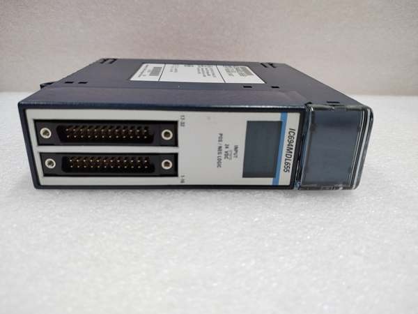
GE IC694MDL655
The Real-World Problem It Solves
Thirty-two inputs in a single slot. That’s the pitch. When panel space is tight and you need to monitor three dozen proximity switches, pushbuttons, and interlocks, this module replaces two standard 16-point cards and frees up a slot for something else. The four-group isolation architecture means you can wire sensors from different power supplies without creating ground loops.
Where you’ll typically find it:
- Distributed I/O racks on conveyor lines aggregating dozens of photoeyes and limit switches
- Material handling sortation systems where one rack monitors multiple conveyor zones
- Machine tool cells consolidating operator station inputs, safety gates, and process interlocks into minimal rack space
Bottom line: Maximum input density per slot with the flexibility of isolated groups—use it when you’re out of rack slots but not out of sensors.
Hardware Architecture & Under-the-Hood Logic
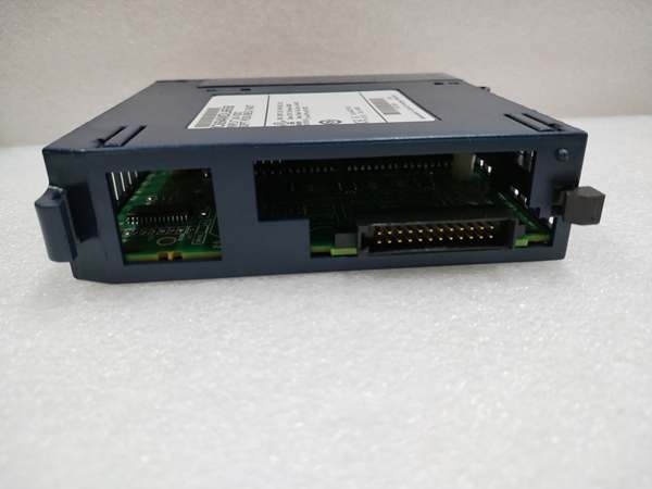
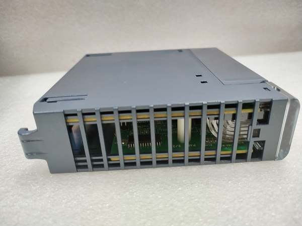
This module uses two 24-pin connectors instead of a terminal block, making it a high-density design. The 32 inputs are divided into four isolated groups of eight. Each group shares a common terminal but is galvanically isolated from the other three groups and from the backplane via optocouplers. There’s no onboard processor—just input conditioning and optical isolation.
Signal flow breakdown:
- Field device connects to one of 32 input pins on the two front-mounted connectors.
- Input current (7mA typical) flows through an optocoupler LED within the assigned group.
- Optocoupler output is latched and read by the CPU during the I/O scan cycle.
- Each group has its own COM terminal and can be wired for positive or negative logic independently.
- The module provides +24V OUT terminals, but using them degrades isolation from 250VAC to 50VAC continuous.
GE IC694MDL655
Field Service Pitfalls: What Rookies Get Wrong
Temperature Derating Catches You at 50°C and AboveThis module has a thermal limit based on how many inputs are on simultaneously. At 60°C ambient, you can only have 8 inputs per group on at 24V supply, or 6 inputs per group at 30V supply. Exceed this and you risk input drift or module failure.
- Field Rule: Before commissioning, audit which inputs are normally on. If you have 10 sensors per group continuously active in a hot cabinet, either move some to a different module or add cooling.
Group-to-Group Isolation is Only 50VACThe 250VAC isolation rating is field-to-backplane. But isolation between the four input groups is only 50VAC continuous. If you wire one group to a 120VAC-referenced circuit and another to a 24VDC-referenced circuit, you can exceed this rating and damage the module.
- Quick Fix: Treat each group as a separate electrical domain. Don’t mix AC-referenced and DC-referenced circuits in different groups unless you verify the potential difference stays below 50VAC.
Connector Wiring Mistakes with IC693CBL327/328 CablesThe module uses Fujitsu FCN-365P024-AU connectors, not standard terminal blocks. Pre-wired cables (IC693CBL327 and IC693CBL328) are available, but if you build your own cables, the pinout is non-intuitive. Inputs are interleaved across the two connectors, not sequential.
- Field Rule: Download the official pinout diagram from the GFK-2314C manual. Never guess—wrong wiring can short multiple inputs together through the common rail.
Commercial Availability & Pricing Note
Please note: The listed price is for reference only and is not binding. Final pricing and terms are subject to negotiation based on current market conditions and availability.


