
Description
Hard-Numbers: Technical Specifications
- Output Channels: 16 points, individually isolated
- Rated Voltage: 120/240VAC (dual-rated)
- Output Voltage Range: 74–265VAC, 47–63Hz
- Output Current Per Point: 2A max @ 30°C / 1A max @ 60°C (linear derating)
- Output Current Per Module: 5A max @ 30°C / 4A max @ 60°C
- Inrush Current: 20A maximum for one AC cycle
- Minimum Load Current: 10mA per point
- Output Voltage Drop: 1.5V maximum
- Off-State Leakage: 2mA maximum
- Response Time: ½ cycle maximum (both ON and OFF)
- Isolation Rating: 250VAC continuous / 1500VAC for 1 minute (field-to-logic, group-to-group)
- Power Draw: 315mA from 5V backplane bus (all outputs ON)
- Operating Temperature: 0°C to +60°C
- Required CPU Firmware: RX3i CPU Release 3.50 or later
- Internal Fusing: None—external fusing required
- Compatible Terminal Blocks: IC694TBB032, IC694TBB132, IC694TBS032, IC694TBS132 (ordered separately)
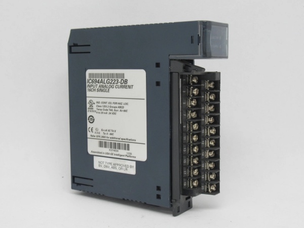
GE IC694ALG223
The Real-World Problem It Solves
You need to switch AC loads across multiple power phases or independent circuits without a single common neutral, and you don’t want a fault on one output to kill the whole card. Traditional relay output cards with shared commons cascade failures—lose one channel to a short, and adjacent channels can get pulled down or produce ghost voltages. This module gives each output its own isolated triac with dedicated supply terminals.
Where you’ll typically find it:
- Motor control center (MCC) output staging where each starter coil runs from a different phase
- Process valve manifolds with 120VAC solenoids powered from separate branch circuits
- Pump station control panels driving multiple contactor coils across A/B power feeds
Bottom line: One output fries, the other fifteen keep running—critical for systems where you can’t afford a total loss of control.
Hardware Architecture & Under-the-Hood Logic
This card uses solid-state triac outputs, not electromechanical relays. Each channel has its own optically-coupled triac driver and built-in RC snubber network. The module doesn’t have an onboard microprocessor—it’s a slave device that receives output commands from the CPU over the backplane serial bus and switches AC power accordingly.
- CPU sends output command over the backplane → the module’s backplane interface ASIC receives the 16-bit output word and latches it into the output buffer.
- Each bit drives an optocoupler LED → when the bit is set (ON), the opto activates, triggering the gate of the corresponding triac.
- Triac conducts AC power → the triac fires at the next zero-crossing (½ cycle max delay), passing current from the external AC supply through the load connected to the output terminal.
- RC snubber clips inductive kickback → an internal resistor-capacitor network absorbs voltage transients from switching inductive loads (contactor coils, solenoids), eliminating the need for external snubbers in most applications.
- On comm loss, the DIP switch determines behavior → Force Off (all outputs drop out) or Hold Last State (triacs maintain position as long as backplane power and AC supply remain).
GE IC694ALG223
Field Service Pitfalls: What Rookies Get Wrong
No Internal Fuses—You’re On Your Own
The spec sheet says “no internal fusing.” That’s not a suggestion. Wire this card straight to a contactor coil without a fuse, and a shorted coil will toast the triac—now you’re swapping the whole module at 2AM. The triac fails shorted, the load stays energized, and you’ve got a safety hazard.
Field Rule: Install a 2A–3A fast-blow fuse (or appropriately sized circuit breaker) on each output’s supply lead. If you’re driving multiple loads from one output, fuse each branch individually. Keep spare fuses in the panel door.
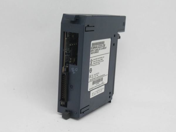
DIP Switch Mismatch Causes Fault Table Warnings
The DIP switch on the back of the card sets the fail-safe mode (Force Off vs. Hold Last State). But you also have to configure this in Proficy Machine Edition under the module’s properties. If the hardware switch and software setting don’t match, the CPU throws a fault table warning every time the rack powers up.
Quick Fix: Before installing the card, pop it out of the backplane and check the DIP switch position. Then match it in PME: Module Configuration → IC694MDL350 → Output Default Mode. Common practice for safety-critical systems: set both to Force Off so outputs drop out on CPU stop or comm loss.
Temperature Derating Will Bite You in Hot Panels
At 30°C, you get 2A per point and 5A per module. At 60°C, that drops to 1A per point and 4A per module. Stuff this card in a sealed NEMA 4 enclosure with no ventilation, load all 16 outputs to 1.8A, and watch the triacs overheat when the panel interior hits 50°C+ during summer.
Field Rule: Calculate your worst-case panel ambient temperature, then derate accordingly. If you’re running hot loads in a hot cabinet, move to a relay output card (IC694MDL330) or add forced-air cooling. Check the panel temperature with an IR gun during commissioning—not just during design.
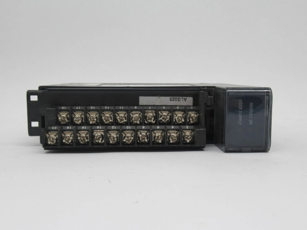
Forgetting the External AC Supply
This card does not power the loads. It switches external AC. The “Supply” terminals on each output pair (e.g., pins 1-2 for Output 1) need to be wired to your AC source. Forget this, and your outputs will show ON status in logic but the field devices won’t budge.
Quick Fix: Each output has two terminals: Output (to load) and Supply (from AC source). You can wire all Supply terminals to a common AC feed if your application allows it, or feed each output from a different phase. Verify AC is present at the Supply terminals with a meter before commissioning.
Commercial Availability & Pricing Note
Please note: The listed price is for reference only and is not binding. Final pricing and terms are subject to negotiation based on current market conditions and availability.


