
Description
Hard-Numbers: Technical Specifications
- Number of Slots: 5 I/O module positions (Slot 1 dedicated to power supply)
- Backplane Bus Type: High-speed serial only—no PCI bus support
- Internal Power Draw: 170 mA @ 5 VDC (0.85 Watts) for backplane logic
- Maximum Expansion Cable Length: 50 feet (15 meters) from CPU backplane
- Expansion Connector: 25-pin D-shell female (right side of chassis)
- Operating Temperature: 0°C to 60°C (32°F to 140°F)
- Compatible Power Supplies: IC694PWR321, IC694PWR330, IC694PWR331
- Dimensions: 5.12″ H × 10.43″ W × 5.59″ D (130 × 245 × 142 mm)
- Weight: 1.25 lbs (0.57 kg)
- Hot Swap Support: Not supported—power down before module installation
- Rack Addressing: DIP switch selection (must set before module insertion)
- Maximum Daisy-Chained Backplanes: Up to 7 serial expansion racks per CPU backplane
- Compatible Universal Backplanes: IC695CHS012 (12-slot), IC695CHS016 (16-slot)
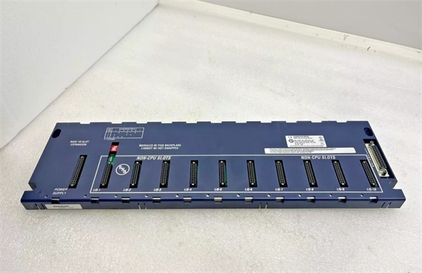
GE IC694CHS392
The Real-World Problem It Solves
When cabinet real estate is tight but you still need distributed I/O, the IC694CHS398 is the answer. It’s half the width of the 10-slot IC694CHS392 (10.43″ vs. 17.44″), which means it fits in those cramped enclosures where a full-size rack won’t go—motor control centers, skid-mounted equipment, and retrofit jobs with zero spare panel space.
Where you’ll typically find it:
- Skid-mounted process equipment where I/O points are clustered in a small physical footprint
- MCC (Motor Control Center) retrofits where panel depth and width are severely limited
- Distributed sensing stations (temperature, pressure) that need 3-4 analog modules plus a communication module
Bottom line: Extends I/O capacity in space-constrained installations where a 10-slot rack is overkill physically and financially.
Hardware Architecture & Under-the-Hood Logic
The IC694CHS398 is a passive serial backplane—no microprocessor, no firmware, no intelligence. It’s purely a mechanical frame with copper traces that route the high-speed serial bus from the CPU backplane through a 25-pin D-shell expansion cable to 5 I/O module slots. Think of it as an electrical extension cord for the backplane bus.
Signal Flow & Physical Layout:
- Expansion Cable Input (Right Side): 25-pin D-shell connector receives the serial bus from the upstream backplane (CPU rack or another expansion rack). Cable part number: IC693CBL302.
- Serial Bus Distribution: Internal PCB traces distribute the high-speed serial signals (data, clock, control lines) to all 5 slots in parallel. Passive bus—no signal conditioning or repeaters.
- Slot 1 Power Supply Position: Leftmost slot is mechanically keyed for a serial expansion power supply. This supply delivers 5VDC backplane power and 24VDC field power to modules installed in Slots 2-5.
- DIP Switch Rack Addressing: A 4-position DIP switch sets the rack number (0-7). The CPU identifies this backplane by this address during hardware configuration. Must be configured before power-up.
- Expansion Output (Optional): Right-side connector can pass the serial bus downstream to another expansion rack in the daisy chain. Total cable length from CPU to final rack cannot exceed 50 feet.
- Termination Requirement: The last backplane in the chain requires a terminating resistor (IC693ACC307) installed at the expansion connector to eliminate signal reflections.
Field Service Pitfalls: What Rookies Get Wrong
Installing Modules Before Setting the DIP Switch
The DIP switch sets the rack address, and the CPU will fail to recognize the backplane if the address conflicts with another rack or is left unconfigured. If modules are already installed when you realize the switch is wrong, you’ll have to pull everything out to fix it.
- Field Rule: Set the DIP switch to the assigned rack number before mounting the backplane or installing any modules. Cross-check against your Proficy Machine Edition hardware configuration.
Assuming Hot-Swap Capability Because It’s RX3i
The RX3i universal backplanes (IC695CHS012/016) support hot insertion and removal, but the IC694CHS398 serial expansion backplane does not. Pulling a module while powered can damage backplane traces, corrupt serial communication, or trigger a CPU fault.
- Quick Fix: Treat this backplane like legacy Series 90-30 hardware. Power down the expansion rack completely before swapping any modules. If hot-swap is a requirement, use a universal backplane instead.
Mixing Up CHS398 with CHS392 Cable Length Requirements
The 50-foot cable limit applies to the entire daisy chain, not just the individual cable between racks. If you have three expansion racks spread across a large enclosure, the total cable length from the CPU to the last rack must not exceed 50 feet.
- Field Rule: Measure cable routing carefully during layout. If your physical layout requires more than 50 feet of total cable, use a remote backplane (IC693CHS399) which supports up to 700 feet, or migrate to Ethernet-based distributed I/O.
Forgetting to Install the Power Supply in Slot 1
The leftmost slot is dedicated to power supply. If you try to install an I/O module there, it won’t fit properly and the backplane won’t have local power. I’ve seen guys waste 30 minutes troubleshooting “dead modules” only to realize they never installed a power supply.
- Quick Fix: Verify a serial expansion power supply (IC694PWR321/330/331) is installed in Slot 1 before powering up. Check that the supply’s output voltage selector matches your field device requirements.
Commercial Availability & Pricing Note
Please note: The listed price is for reference only and is not binding. Final pricing and terms are subject to negotiation based on current market conditions and availability.


