
Description
Hard-Numbers: Technical Specifications
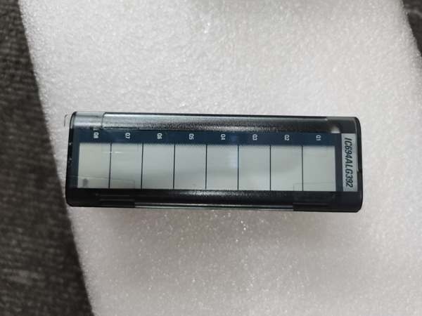
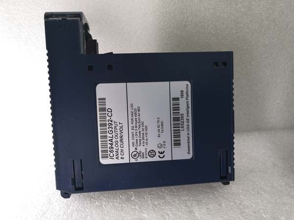
- Output Channels: 8 single-ended, individually configurable (1-8 active)
- Current Output Ranges: 4-20 mA, 0-20 mA
- Voltage Output Ranges: 0 to +10 V (unipolar), -10 to +10 V (bipolar)
- Resolution: 15 bits (unipolar), 16 bits (bipolar voltage)
- Update Rate: 8 milliseconds (all 8 channels)
- Absolute Accuracy: ±0.1% FS (current, 25°C typical); ±0.25% FS (voltage, 25°C typical)
- Load Capacity (Current Mode): 850Ω @ 20V user supply; up to 1350Ω @ 30V user supply
- Isolation Rating: 250 VAC continuous / 1500 VAC for 1 minute (field-to-backplane, optical)
- Power Consumption: 110 mA from +5 VDC backplane; 315 mA from external +24 VDC user supply
- External Supply Range: 20-30 VDC (ripple max 10%)
- Operating Temperature: 0°C to +60°C (32°F to 140°F)
GE IC694ALG392
The Real-World Problem It Solves
When your cabinet layout can’t afford eight separate output modules for a mixed bag of current and voltage devices, this board does the job in one slot. You get eight software-configurable channels that can drive 4-20mA valve positioners on half the outputs and 0-10V servo references on the other half—no rewiring, no hardware swaps.
Where you’ll typically find it:
- Process skids with proportional valves (4-20mA) and VFDs (0-10V) sharing the same I/O rack
- Paper machine drives where tension controls need voltage outputs while flow loops need current
- Utility plants feeding analog references to legacy DCS front-ends
Bottom line: One module, eight channels, current or voltage per channel. That flexibility saves panel space and spares inventory.
Hardware Architecture & Under-the-Hood Logic
The IC694ALG392-FG doesn’t have its own on-board processor for signal generation. It relies on the RX3i CPU to write 16-bit integer values to each channel’s output reference address (%AQ). The module’s internal DAC converts those counts to analog levels based on the configured range.
Signal flow, step-by-step:
- CPU Write: The PLC logic writes a 16-bit signed integer (0 to 32767 for unipolar, -32768 to +32767 for bipolar) to the %AQ address assigned to each channel.
- Range Scaling: The module’s DAC maps the count to the configured output range (e.g., 0 = 4 mA, 32000 = 20 mA).
- Output Drive: In current mode, the module sources loop current from the external +24 VDC supply through an internal current driver. In voltage mode, it drives voltage directly into the load.
- Fault Detection (Current Mode Only): The module monitors loop continuity. If the loop opens, it sets a broken-wire fault bit in the status word (%I reference) and can hold the last state or default to zero.
- Update Cycle: All eight channels refresh every 8 ms, synchronized to the I/O scan.
GE IC694ALG392
Field Service Pitfalls: What Rookies Get Wrong
External Power Confusion
Rookies assume the module gets all its power from the backplane. It doesn’t. The +24 VDC user supply is mandatory for any channel to output current or voltage. If the USER OK LED is off, you’ll get zero output even if the module is configured and the OK LED is on.
- Field Rule: Verify +24 VDC at the TB1 connector (universal backplane) or at the module’s terminal block (expansion backplane) before chasing output faults. Measure it under load.
Broken-Wire Diagnostics Not Enabled
The module can detect open loops in current mode, but that status data isn’t automatic. You have to configure 16 bits of status input (%I reference) to see the broken-wire bits for channels 1-8. If you only configure 8 bits, you get module status but no per-channel fault visibility.
- Quick Fix: In Proficy Machine Edition, set the status data length to 16 bits and map the %I reference. Bits 9-16 are the broken-wire indicators for channels 1-8.
Load Resistance Overload in Current Mode
The maximum load isn’t fixed. It depends on your user supply voltage. At 20 VDC, you get 850Ω max. At 30 VDC, you can push to 1350Ω. If you’re at 24 VDC nominal and try to drive a 1000Ω load, you’re on the edge—loop voltage drops, and output accuracy degrades or the loop opens.
- Field Rule: Calculate (VUSER – 3V) / Imax to get your compliance voltage headroom. If the load resistance times the max current exceeds that, you need a higher user supply voltage or a lower-resistance loop.
Commercial Availability & Pricing Note
Please note: The listed price is for reference only and is not binding. Final pricing and terms are subject to negotiation based on current market conditions and availability.


