

Description
Hard-Numbers: Technical Specifications
| Parameter | Specification |
|---|---|
| Number of Output Channels | 1 to 8 selectable, single-ended |
| Output Current Range | 4 to 20 mA, 0 to 20 mA |
| Output Voltage Range | 0 to +10 V (unipolar), -10 V to +10 V (bipolar) |
| Resolution | 4-20mA: 0.5 µA/bit (15-bit); 0-20mA: 0.625 µA/bit (15-bit); 0-10V: 0.3125 mV/bit (15-bit); -10 to +10V: 0.3125 mV/bit (16-bit) |
| Update Rate | 8 milliseconds (all eight channels) |
| Absolute Accuracy – Current Mode | ±0.1% of full scale @ 25°C (typical); ±0.25% of full scale @ 25°C (maximum); ±0.5% of full scale over operating temperature range (maximum) |
| Absolute Accuracy – Voltage Mode | ±0.25% of full scale @ 25°C (typical); ±0.5% of full scale @ 25°C (maximum); ±1.0% of full scale over operating temperature range (maximum) |
| Maximum Compliance Voltage | VUSER – 3V (minimum) to VUSER (maximum) |
| User Load (Current Mode) | 0 to 850 Ω (minimum at VUSER = 20V); maximum 1350 Ω at VUSER = 30V (Load < 800Ω is temperature dependent) |
| Output Load Capacitance (Current Mode) | 2000 pF (maximum) |
| Output Load Inductance (Current Mode) | 1 H |
| Output Loading (Voltage Mode) | 5 mA (2 KΩ minimum resistance) |
| Output Load Capacitance (Voltage Mode) | 1 µF maximum |
| Isolation | 250 VAC continuous; 1500 VAC for 1 minute (field to backplane, optical and frame ground) |
| Internal Power Consumption | 110 mA from +5 VDC PLC backplane supply; 315 mA from +24 VDC user supply |
| External Supply Voltage Range | 20 VDC to 30 VDC |
| External Power Supply Voltage Ripple | 10% (maximum) |
| Power Supply Rejection Ratio (PSRR) – Current | 5 µA/V (typical), 10 µA/V (maximum) |
| Power Supply Rejection Ratio (PSRR) – Voltage | 25 mV/V (typical), 50 mV/V (maximum) |
| LED Indicators | Module OK, User Supply OK |
| Weight | 0.69 lbs (0.31 kg) |
| Compatible PLC Systems | RX3i PACSystems, Series 90-30, Series 90-70 |
| Approvals | UL, UL HAZLOC, CE, ATEX C1D2, ABS, BV, DNV, GL, KRS, LR |
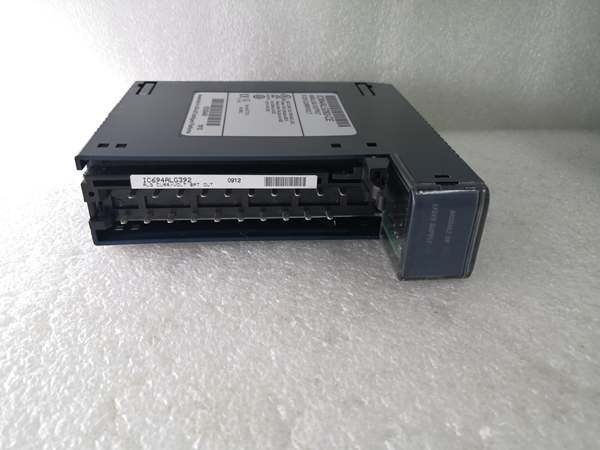
GE IC694ALG392
The Real-World Problem It Solves
This module provides flexible analog output capability with four configurable signal ranges and built-in fault detection, eliminating the need for multiple dedicated voltage or current output modules. Its open-wire detection in current mode and last-value hold feature enhance process safety during power interruptions or wiring failures.
Where you’ll typically find it:
- Chemical processing plants controlling modulating control valves for flow and pressure regulation
- HVAC systems driving variable speed drives and damper actuators
- Water treatment facilities controlling chemical dosing pumps and mixing agitators
- Oil & gas platforms positioning pneumatic actuators and hydraulic control systems
Bottom line: It’s your versatile multi-range analog output solution for precise actuator control in process automation applications, with diagnostic capabilities that reduce downtime and enhance system reliability.
Hardware Architecture & Under-the-Hood Logic
The IC694ALG392 contains eight independent output circuits with individual DACs (Digital-to-Analog Converters) and optical isolation between the PLC backplane and field devices. Each channel is software-configurable for the four output ranges, with the module providing 15-bit or 16-bit resolution depending on the selected range.
Signal flow breakdown:
- PLC CPU sends digital output value to module via backplane (16-bit integer)
- Module validates data against configured range limits (e.g., 0-32767 for 0-10V)
- Digital value passes through optical isolation barrier (protecting backplane)
- DAC converts digital signal to analog (voltage or current)
- Output amplifier provides final signal conditioning (current loop driver or voltage buffer)
- Analog signal routed to appropriate terminal (V CHx or I CHx)
- Internal circuitry monitors output for open-wire condition (current mode only)
- Status bits updated in dual-port memory (module OK, power OK, broken wire per channel)
- PLC CPU reads status bits during scan cycle for diagnostic purposes
- LED drivers illuminate MODULE OK and USER SUPPLY indicators
Data scaling from PLC to output:
- 4-20mA: 0 counts = 4 mA, 32000 counts = 20 mA (15-bit resolution)
- 0-20mA: 0 counts = 0 mA, 32000 counts = 20 mA (15-bit resolution; up to 32767 provides ~20.5 mA)
- 0-10V: 0 counts = 0V, 32000 counts = +10V (15-bit resolution; up to 32767 provides ~10.24V)
- -10 to +10V: -32000 counts = -10V, +32000 counts = +10V (16-bit resolution; full range -32768 to +32767)
Status bit allocation (first 16 bits):
- Bits 1-8: Module diagnostics (Module OK, Power OK, Reserved)
- Bits 9-16: Channel 1-8 broken wire status (current mode only; 1 = wire broken, 0 = OK)
Power-fail behavior (configurable):
- Hold last value: Outputs maintain last valid output when external 24VDC is interrupted
- Reset to zero: Outputs default to 0V/0mA on power interruption

GE IC694ALG392
Field Service Pitfalls: What Rookies Get Wrong
Mixed Load Wiring ErrorsTechnicians connect both voltage and current outputs to the same channel terminals simultaneously, expecting both signals to function simultaneously.
- Field Rule: Each channel can operate as EITHER voltage output OR current output, not both simultaneously. Configure software range before wiring. Use V CHx terminal for voltage, I CHx terminal for current.
Compliance Voltage MiscalculationEngineers install current loop devices with total impedance exceeding module’s compliance voltage capability, causing output saturation or inability to reach 20 mA.
- Field Rule: Calculate total loop resistance: transmitter input impedance + wire resistance. At 24V supply, maximum load is 850Ω. At 30V supply, maximum load is 1350Ω. Add safety margin of 15-20% for voltage drops under temperature extremes.
Open-Wire Detection DisabledTeams configure 4-20mA outputs but don’t enable broken wire diagnostics in status bits, missing valuable fault information during maintenance.
- Field Rule: Always configure status bit length to 16 bits in current mode. Bits 9-16 report broken wire status per channel. Monitor these bits in HMI or PLC program for real-time fault indication.
Power Supply UndersizingInstallers use undersized 24VDC power supplies (<500mA) to power multiple ALG392 modules, causing voltage sag and output inaccuracy during peak load.
- Field Rule: Each ALG392 draws 315mA from 24VDC supply + loop current. For 4 modules, supply minimum 1.5A + loop current. Calculate: (315mA × module count) + (20mA × active loops × 1.25 safety factor).
Last-Value Hold MisconfigurationProgrammers set outputs to “reset to zero” on power loss in critical process applications, causing unsafe valve positions during power interruptions.
- Field Rule: Configure power-fail behavior to “hold last value” for process control applications (valves, dampers, pumps). Only use “reset to zero” for bench testing or non-critical test equipment.
Inductive Load Flyback DamageTechs connect solenoid valves or relay coils directly to current outputs without flyback protection, causing module damage from voltage spikes.
- Field Rule: Install flyback diode across inductive loads (cathode to positive, anode to negative). For current outputs, add 100-200Ω series resistor + diode to limit inductive kickback within module’s 1H inductance rating.
Ground Loops in Voltage ModeInstallers ground VCOM terminal at both PLC cabinet and remote equipment, creating ground reference differences causing inaccurate voltage outputs.
- Field Rule: Ground VCOM at PLC cabinet only. Use shielded twisted-pair cable for voltage outputs, grounding shield at cabinet end. Float remote equipment VCOM when possible to eliminate ground loops.
Capacitive Load OscillationEngineers connect long cable runs (>100 meters) to current outputs without considering cable capacitance, causing output oscillation or instability.
- Field Rule: Limit cable capacitance to 2000pF per channel. For long runs: (a) use low-capacitance cable (30-50pF/m), (b) add RC snubber at module terminals, or (c) switch to voltage mode with local loop converter.
Status Bit Address ConflictsProgrammers allocate status bits starting at %I0001, overwriting discrete inputs and causing intermittent system failures.
- Field Rule: Allocate unique status word for analog modules. Example: Use %I0017-%I0032 for ALG392 status bits (8 or 16 bits). Document address assignments in I/O map to prevent conflicts.
Power-Fail Hold vs. Reset ConfusionNew techs don’t understand that external 24VDC must remain applied for “hold last value” function to work, assuming the 5V backplane power is sufficient.
- Field Rule: Hold last value only works if external 24VDC supply remains powered during PLC backplane power loss. For complete system power loss, both backplane and external power fail, and outputs cannot hold regardless of configuration.
Please note: The listed price is for reference only and is not binding. Final pricing and terms are subject to negotiation based on current market conditions and availability.


