
Description
Hard-Numbers: Technical Specifications
- Output Channels: 2 (independent)
- Current Range: 0-20 mA or 4-20 mA (jumper selectable per channel)
- Voltage Range: 0-5V or 1-5V (reduced accuracy, jumper or 250Ω resistor)
- Resolution: 12-bit (4 μA/count for 4-20mA; 5 μA/count for 0-20mA)
- Update Rate: 5 milliseconds (both channels)
- Accuracy (Current): ±8 μA at 25°C (4-20mA); ±10 μA (0-20mA)
- Accuracy (Voltage): ±50 mV at 25°C
- Maximum Load (Current Mode): 0 to 850 Ω
- Maximum Load (Voltage Mode): 5 mA (minimum 2 kΩ resistance)
- Compliance Voltage: 25 VDC maximum
- Isolation Rating: 250VAC continuous; 1500VAC for 1 minute (field-to-backplane, optical)
- Internal Power Draw: 30 mA from +5VDC backplane; 215 mA from isolated +24VDC
- External Power Required: Isolated +24VDC (20-30VDC, 10% max ripple)
- Operating Temperature: 0°C to +60°C (+32°F to +140°F)
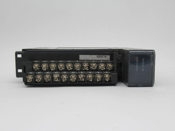
- Terminal Block: 20-screw, included (accepts AWG 14-22)
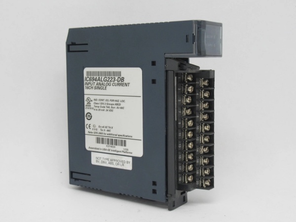
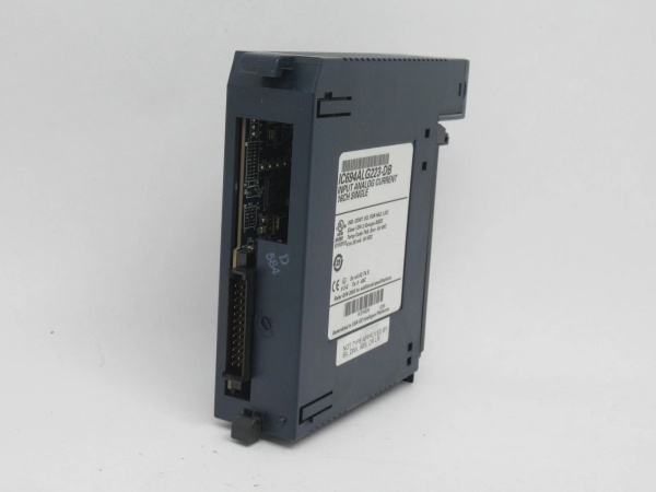
GE IC694ALG223
The Real-World Problem It Solves
Process loops need precision current signals to drive final elements—control valves, variable frequency drives, indicator loops. This module takes 12-bit digital values from the PLC and converts them to clean 4-20mA or 0-20mA outputs that field devices can actually use. No messing with external signal conditioners or loop-powered isolators for basic applications.
Where you’ll typically find it:
- Control valve positioners requiring 4-20mA command signals
- VFD speed reference inputs (0-20mA or 4-20mA scaling)
- Chart recorders and panel meters on process skids
- Simple dosing pump speed controls
Bottom line: Two reliable current loops in a single-slot package, jumper-configurable for range and fail-safe behavior.
Hardware Architecture & Under-the-Hood Logic
This module does not have an onboard microprocessor. It’s a dumb DAC—digital-to-analog converter—controlled entirely by the CPU. The PLC writes 16-bit signed values to the %AQ registers, the module strips the 13 most significant bits, converts to analog, and drives the output current sources. Isolation is handled optically between field side and backplane.
Signal path, step-by-step:
- CPU writes commanded output value to %AQ register (16-bit two’s complement format).
- Module receives the 13 most significant bits via backplane bus.
- Internal DAC converts digital word to analog voltage reference.
- Output driver stages produce current (or voltage) based on jumper configuration.
- Isolated +24VDC powers the output driver circuits—not the backplane 5V rail.
- Output current loops through field device and returns to module common.
No channel-to-channel isolation. Both outputs share a common isolated power domain. If you need per-channel isolation, you’re looking at the wrong module—grab an IC695ALG808 instead.
GE IC694ALG223
Field Service Pitfalls: What Rookies Get Wrong
External 24V Power Is Mandatory on Universal Backplanes
Rookies assume the module pulls all power from the backplane. On an RX3i Universal Backplane, the isolated +24VDC rail doesn’t exist internally—you must bring external power. Connect via TB1 on the backplane left side or land it directly on the module terminal block. Without it, the Module OK LED won’t even light.
Field Rule: Before racking the module, trace your +24VDC source. Verify it’s isolated from plant ground—shared grounds will inject noise into your current loops.
Hold-Last-State Requires External Power
The output default jumper (terminals 11 and 13) sets fail-safe behavior. Jumper installed = outputs drop to 0mA or 4mA on CPU stop. Jumper removed = outputs hold last value. Here’s the catch: hold-last-state cannot work without external +24VDC. If backplane power dies and you have no external supply, the outputs die too—no holding anything.
Quick Fix: If your process needs a controlled hold position on power loss, add a small DIN-rail 24VDC supply dedicated to analog modules. Fuse it separately.
Voltage Mode Accuracy Takes a Hit
You can configure this module for voltage output (0-5V or 1-5V) by installing a jumper between JMPVx and IOUTx terminals—or use a 250Ω resistor in the jumper position. But the specs don’t lie: ±50 mV accuracy versus ±8 μA on current. That’s a 10x relative degradation. Voltage mode is a “good enough” feature, not a precision feature.
Field Rule: If voltage output is your primary requirement, use the IC694ALG390 instead—it’s optimized for voltage with better specs.
No Hot Swap—Power Down First
This module predates the hot-swap era. Pulling it live can arc the backplane connector pins, damage the isolation barrier, or crash the CPU bus. I’ve seen techs fry backplane traces trying to swap modules on a running system.
Field Rule: Rack power off. Wait 30 seconds for capacitor discharge. Then swap. If you need live insertion, move up to IC695ALG-series hardware.
Commercial Availability & Pricing Note
Please note: The listed price is for reference only and is not binding. Final pricing and terms are subject to negotiation based on current market conditions and availability.


