
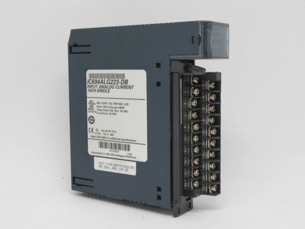
Description
Hard-Numbers: Technical Specifications
| Parameter | Specification |
|---|---|
| Input Channels | 16 single-ended inputs |
| Current Ranges | 0-20 mA, 4-20 mA (standard), 4-20 mA (Enhanced) |
| Resolution | 12-bit (4 µA/count for 4-20 mA; 5 µA/count for 0-20 mA and 4-20 mA Enhanced) |
| Update Rate | 13 milliseconds (all 16 channels) |
| Absolute Accuracy | ±0.25% of full scale @ 25°C (77°F); ±0.5% of full scale over operating temperature range |
| Input Impedance | 250 ohms |
| Low Pass Filter Response | 19 Hz |
| Isolation | 250 VAC continuous; 1500 VAC for 1 minute (field to backplane) |
| Cross-Channel Rejection | > 80 dB from DC to 1 kHz |
| Internal Power Consumption | 120 mA from +5 VDC bus on backplane; 65 mA from 24 VDC external user power supply |
| External Supply Voltage Range | 20 to 30 VDC (10% ripple) |
| Operating Temperature | 0°C to 60°C (32°F to 140°F) |
| Common Mode Voltage | 0 volts (single-ended channels) |
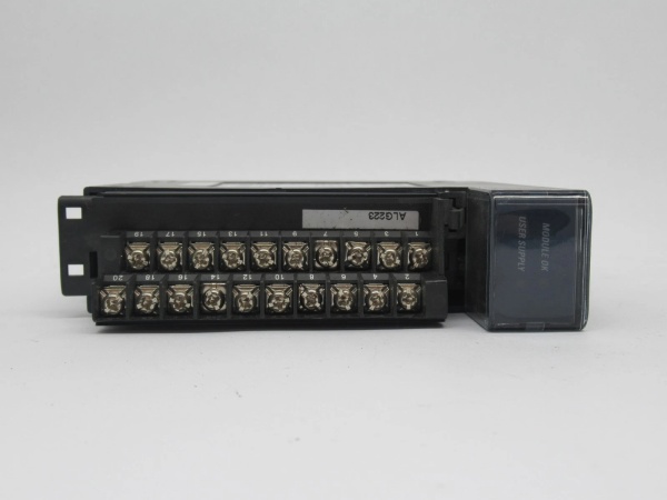
| LED Indicators | Module OK, User Supply OK |
| Weight | 1.13 lbs (0.51 kg) |
| Approvals | UL, UL HAZLOC, CE, ATEX C1D2, ABS, BV, DNV, GL, KRS, LR |
IC694ALG223
The Real-World Problem It Solves
This module provides high-density analog input capability with three configurable current ranges and open-wire fault detection, eliminating the need for multiple lower-density modules while protecting critical process measurements from wiring failures. Its enhanced 4-20mA mode detects open-circuit conditions (current dropping below 4mA to 0mA), enabling proactive maintenance before process deviations occur.
Where you’ll typically find it:
- Chemical processing plants monitoring pressure transmitters and flow meters
- Water treatment facilities tracking level transmitters and flow sensors
- Oil & gas platforms interfacing with temperature transmitters and differential pressure cells
- Pharmaceutical manufacturing with precise process parameter control
Bottom line: It’s your high-density solution for accurate, reliable 4-20mA signal acquisition with built-in diagnostics for mission-critical process applications.
Hardware Architecture & Under-the-Hood Logic
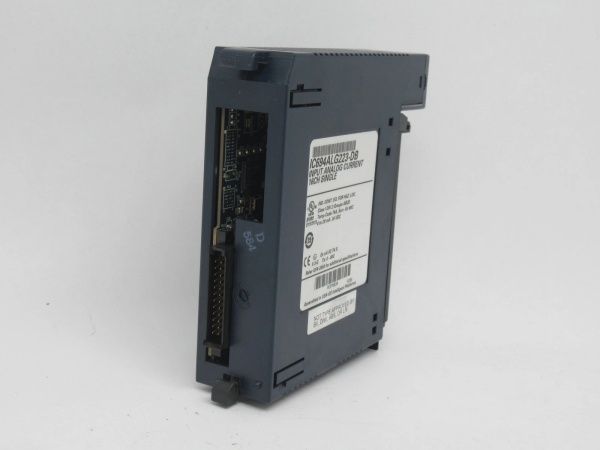
The IC694ALG223 contains 16 independent single-ended input circuits with individual 12-bit ADCs and optical isolation between field wiring and the PLC backplane. Each channel is software-configurable for the three input ranges, with the Enhanced 4-20mA mode providing negative value output for open-wire detection.
Signal flow breakdown:
- Field transmitter applies 4-20mA or 0-20mA signal to input terminal
- Input current passes through 250-ohm precision shunt resistor (converting to voltage)
- Low-pass filter (19 Hz) removes high-frequency noise
- Opto-coupler provides isolation between field side and logic side
- Isolated signal feeds to 12-bit Sigma-Delta ADC (one per channel)
- Digital signal processed by microprocessor with configurable range scaling
- 12-bit ADC value stored in module’s dual-port memory
- Status bits (module OK, power OK, channel alarms) updated
- PLC CPU reads all 16 channel values during scan cycle via backplane
- User Supply LED confirms external 24VDC meets specifications (20-30VDC)
Data scaling in CPU:
- 4-20mA (standard): 4mA = 0 counts, 20mA = 32000 counts
- 0-20mA: 0mA = 0 counts, 20mA = 32000 counts
- 4-20mA (Enhanced): 0mA = -8000 counts, 4mA = 0 counts, 20mA = +32000 counts
Status bit allocation (first 40 bits):
- Bits 1-8: Module diagnostics (Module OK, Power OK, etc.)
- Bits 9-24: Channel 1-8 high/low alarm status
- Bits 25-40: Channel 9-16 high/low alarm status

IC694ALG223
Field Service Pitfalls: What Rookies Get Wrong
Incorrect Range ConfigurationTechnicians configure 4-20mA transmitters using the standard range instead of Enhanced mode, missing open-wire fault detection capability.
- Field Rule: Always use 4-20mA Enhanced mode for loop-powered transmitters where open-circuit detection is critical. Configure low alarm to trigger when current drops below 3.8mA (approximately -1000 counts).
External Power Supply OversizingEngineers install high-capacity 24VDC supplies (>10A) without current limiting, risking module damage during short circuits.
- Field Rule: Use dedicated 24VDC supply sized for total loop current (typically <2A for 16 loops). Add overcurrent protection (PMB or fuse rated 125-150% of total expected loop current).
Common Mode Noise IgnoranceInstallers run input cables in same conduit as VFD output cables, causing cross-channel interference and inaccurate readings.
- Field Rule: Route analog input cables in separate metallic conduit or shielded twisted-pair cable with drain wire grounded at PLC cabinet only. Maintain >12 inches separation from power cables.
Grounding Multiple Sensors to Same PointTechs ground shield wires at both transmitter and module ends, creating ground loops that introduce measurement errors.
- Field Rule: Ground shields at PLC cabinet only. Float shields at transmitter end when possible. Verify common mode voltage remains <1V at module input terminals.
Ignoring Temperature EffectsTeams calibrate modules at room temperature (25°C) without accounting for accuracy drift at elevated process temperatures (>40°C).
- Field Rule: Use Enhanced mode for critical applications requiring ±0.25% accuracy. Budget for ±0.5% full-scale accuracy over entire operating temperature range (0-60°C).
Channel Active Count MismatchProgrammers configure Active Channels to scan all 16 inputs when only 12 are physically wired, wasting CPU scan time and causing confusing alarm status bits.
- Field Rule: Set Active Channels to exact number of wired inputs. Unused channels consume scan resources but report meaningless alarm data.
Input Impedance MismatchInstallers connect sensors with loop resistance exceeding 250 ohms total, causing voltage compliance issues and measurement errors.
- Field Rule: Calculate total loop resistance: transmitter internal resistance + wire resistance + module input impedance (250Ω). Ensure 24VDC supply minus total loop drop maintains >12V at transmitter for loop-powered devices.
Alarm Limit MisconfigurationEngineers set high/low alarm limits inappropriate for selected range (e.g., configuring 4-20mA limits when using 0-20mA range).
- Field Rule: Match alarm limits to selected input range. For 4-20mA Enhanced, allow low alarm from -8000 to +32759 counts to detect open-wire conditions (0mA = -8000 counts).
Please note: The listed price is for reference only and is not binding. Final pricing and terms are subject to negotiation based on current market conditions and availability.


