
Description
Hard-Numbers: Technical Specifications
- Input Channels: 16 single-ended (no differential option)
- Current Ranges: 0-20mA, 4-20mA (standard), 4-20mA Enhanced (selectable per channel)
- Resolution: 12-bit; 4µA/count (4-20mA) / 5µA/count (0-20mA and Enhanced)
- Update Rate: 13ms (all 16 channels scanned)
- Accuracy: ±0.25% of full scale @ 25°C (77°F)
- Input Impedance: 250Ω (precision resistor, inherent to current measurement)
- Isolation Rating: 250VAC continuous / 1500VAC for 1 minute (field-to-backplane, optical)
- Cross-Channel Rejection: >80dB from DC to 1kHz
- Input Filter: 19Hz low-pass
- Common Mode Voltage: 0V (single-ended reference)
- Operating Temperature: 0°C to +60°C (32°F to 140°F)
- Power Draw: 120mA @ +5VDC (backplane) + 65mA @ +24VDC isolated (external supply required)
- External Supply Range: 20-30VDC, 10% ripple max
- Hot Swap: Yes—module can be replaced under power
- Certifications: UL, CE, ATEX, Class I Div 2, marine (ABS, BV, DNV, GL, LR)
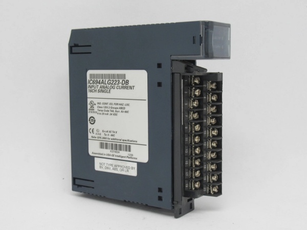
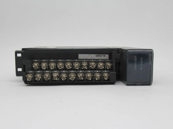
GE IC694ALG223
The Real-World Problem It Solves
You’ve got a dozen 4-20mA transmitters—pressure, flow, level, temperature—and you need to know when a wire breaks. Standard 4-20mA input cards read 4mA as zero scale. If the loop opens, you get 0mA, which looks like -25% of range on a standard card. The ALG223’s Enhanced mode maps 0mA to -8000 counts, letting you set a low alarm below 4mA. Now a broken wire triggers an alarm before the process runs away.
Where you’ll typically find it:
- Offshore platforms reading downhole pressure transmitters (4-20mA with wire-break detection)
- Refinery distillation columns monitoring multiple level transmitters
- Power plant boiler drum level loops where sensor failure must be caught instantly
Bottom line: If you’re wiring 16 current loops and need open-wire detection without external relays, this is your card.
Hardware Architecture & Under-the-Hood Logic
The ALG223 is a pure current-input module—no voltage ranges, no differential mode. It uses precision 250Ω shunt resistors to convert loop current to voltage, then digitizes with a multiplexed 12-bit ADC. The module does not power the loops; it only measures current flowing through them. Your 24VDC external supply powers the transmitters and provides the loop current.
Signal path step-by-step:
- Field wiring terminates at a terminal block (included). Each input connects to a 250Ω precision resistor. Current flowing through creates a voltage drop: 4mA = 1V, 20mA = 5V.
- The voltage across the resistor feeds a multiplexer, which selects one channel at a time for conversion. No per-channel ADC—just one shared converter.
- A 12-bit successive-approximation ADC digitizes the voltage, giving 4096 counts over the range. Factory calibration trims this to 4000 counts for clean scaling.
- Optical isolation separates field-side from backplane logic—250VAC continuous working, 1500VAC test. All channels share a common internal ground.
- The CPU reads the converted value on the next I/O scan. In Enhanced mode, values below 4mA appear as negative counts, enabling broken-wire detection.

GE IC694ALG223
Field Service Pitfalls: What Rookies Get Wrong
No Differential Mode—Single-Ended OnlyUnlike the ALG222 voltage card, the ALG223 offers no differential wiring option. All 16 channels share a common ground reference at the module. If your transmitters are grounded at different potentials in the field, you can create ground loops. Most 2-wire (loop-powered) transmitters float relative to ground, so this works fine. But 4-wire transmitters with grounded outputs will cause offset errors or damage.
- Field Rule: Use isolated signal conditioners on 4-wire transmitters, or verify they’re floating. Never assume ground compatibility between field devices.
External 24VDC Supply Is Not OptionalThis module needs external +24VDC to power its input circuitry—65mA plus the sum of all loop currents. In a Universal Backplane (main rack), you must connect an external supply to TB1. In an expansion rack, the backplane supply provides it. I’ve seen guys chase dead channels for hours because the “User Supply” LED was off and they didn’t notice.
- Quick Fix: Check the USER SUPPLY LED before troubleshooting channels. If it’s off, your external 24V is missing or below 20V.
4-20mA Enhanced Mode ScalingRookies configure Enhanced mode expecting the same scaling as standard 4-20mA. In Enhanced, 4mA = 0 counts, 20mA = 32000 counts—but 0mA = -8000 counts. If your HMI scaling assumes 0-32000, you’ll see negative values on broken wires. That’s the feature, not a bug. But if you’re not using the alarm, you’ll confuse operators.
- Field Rule: Only use Enhanced mode if you’re configuring low alarms below 4mA. Standard 4-20mA mode scales 4mA to 0 and works fine for most applications.
Input Impedance Is Fixed at 250ΩCurrent input modules don’t have “high impedance”—they use precision resistors. 250Ω at 20mA dissipates 100mW per channel. With all 16 channels at 20mA, that’s 1.6W of heat in the terminal area. In a hot cabinet, this adds up. The module is rated to 60°C ambient, but marginal cooling will drift the calibration.
- Field Rule: If your cabinet runs above 50°C, derate channel count or add ventilation. Don’t stuff this card between high-power modules.
Commercial Availability & Pricing Note
Please note: The listed price is for reference only and is not binding. Final pricing and terms are subject to negotiation based on current market conditions and availability.


