
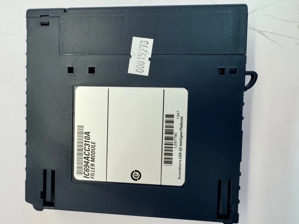
Description
Hard-Numbers: Technical Specifications
- Channels: 4 analog inputs (single-ended)
- Voltage Range: -10 to +10 VDC
- Current Input: 4-20 mA (jumper terminals per channel)
- Resolution: 12-bit (5 mV/bit, 20 µA/bit)
- Conversion Speed: 1 ms per channel
- Update Rate: 4 ms for all four channels
- Input Filter Response: 17 Hz fixed
- Power Draw: 27 mA @ +5VDC (backplane) + 98 mA @ +24VDC isolated
- Cross-Channel Rejection: >80 dB
- Calibration: Factory calibrated (no field adjustment required)
- Hot Swap: Not supported—power down before insertion/removal
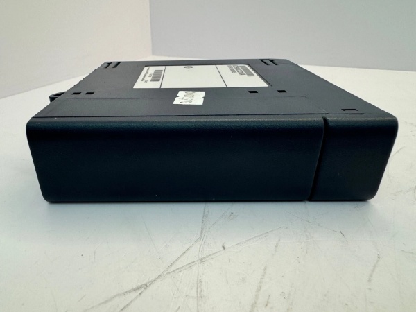
GE IC694ACC310
The Real-World Problem It Solves
You’ve got field devices putting out standard voltage or current signals, and your PLC needs to read them accurately without dedicating separate cards for each signal type. This module handles both -10V to +10V and 4-20mA on the same hardware, which saves panel space and reduces spare parts inventory.
Where you’ll typically find it:
- Process control loops reading valve position feedback (4-20mA from positioners)
- Drive speed reference signals (±10V from motion controllers)
- Level/pressure transmitter inputs in water treatment plants
If you need four analog points and don’t want to burn a high-density card, this is your go-to.
Hardware Architecture & Under-the-Hood Logic
This is a dumb input card—no onboard microprocessor. It relies on the RX3i CPU for all signal processing. The isolation is channel-to-backplane only, not channel-to-channel, so all four inputs share a common reference.
- Field Signal Arrival – Voltage or current enters via screw terminals. If using 4-20mA mode, you must jumper the input terminals on that channel to route current through the internal 250Ω burden resistor.
- Analog-to-Digital Conversion – A multiplexer scans each channel sequentially. Each conversion takes 1 ms. The 12-bit ADC outputs a raw count value to the backplane.
- Backplane Communication – The module pushes data to the CPU every 4 ms. No configuration memory on the card—all scaling, engineering units, and alarm limits live in the PLC program.
Field Service Pitfalls: What Rookies Get Wrong
Hot-Swapping This CardRookies see other RX3i modules with hot-swap capability and assume this one does too. It doesn’t. Pulling it live can spike the backplane bus and corrupt data in adjacent slots.
- Field Rule: Always confirm power is off at the power supply before seating or removing this module. If you need hot-swap capability, look at the IC695 series instead.
Jumpering for 4-20mA ModeThe manual shows jumper positions, but guys in the field forget that each channel needs its own jumper. Miss one, and you’ll read garbage—usually rail-to-rail noise.
- Quick Fix: Verify jumper wire is installed across terminals 1-2 on each channel configured for current input. Use 18-22 AWG solid wire, not stranded (stray strands cause intermittent shorts).
Shield Grounding at Both EndsField techs sometimes ground the shield at both the transmitter and the module. That creates a ground loop, and you’ll see 60 Hz noise riding on your signal.
- Field Rule: Ground the shield at one end only—typically at the module side (GND terminal) or the source side, never both. For floating sources, tie the (-) side to the COM terminal to limit common-mode voltage.
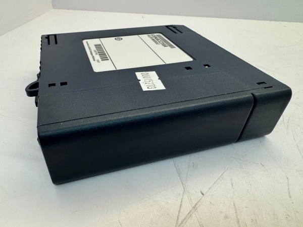
GE IC694ACC310
Commercial Availability & Pricing Note
Please note: The listed price is for reference only and is not binding. Final pricing and terms are subject to negotiation based on current market conditions and availability.


