
Description
Hard-Numbers: Technical Specifications
- Cable Type: Parallel cable assembly with shielding
- Length: 1.5 meters (5 feet) – extended version of IC694ACC300 (1 meter)
- Connector Type: Specialized GE parallel interface connectors (CPU end and backplane end)
- Wire Gauge: 24-26 AWG for signal conductors, 22 AWG for power/ground
- Shielding: Overall foil shield + drain wire for EMI protection
- Operating Temperature: -40°C to +70°C
- Voltage Rating: 30V DC maximum for signal conductors
- Current Rating: 1A maximum per conductor
- Flexibility: Multi-stranded copper conductors for industrial cable routing
- Jacket Material: PVC or thermoplastic elastomer (oil-resistant variants available)
- Color Coding: Typically gray jacket with connector keying to prevent incorrect insertion
- Compatibility: RX7i CPUs (IC697CPUxxx), 90-70 CPUs (IC697CPU7xx/IC697CPU9xx)
- Pin Count: High-density parallel interface (40+ positions depending on connector type)
- Minimum Bend Radius: Approximately 1 inch (2.5 cm) – 4-5x cable diameter
GE IC694ACC310
The Real-World Problem It Solves
Standard 1-meter parallel cables (IC694ACC300) don’t reach when you need to mount the CPU in a separate enclosure or control cabinet from the I/O backplane. In retrofit projects where you’re installing a new RX7i CPU in an existing 90-70 system, physical cabinet layouts often force separation. The ACC310’s 1.5-meter length gives you extra reach without signal degradation—eliminating the need for custom cable builds or expensive extension solutions.
Where you’ll typically find it:
- Control Room to Equipment Room Installations: CPU mounted in climate-controlled control room, I/O backplane in harsh equipment room with motors and VFDs. 1.5-meter ACC310 bridges the gap through conduit while maintaining signal integrity.
- Cabinet Retrofit Projects: Upgrading old 90-70 systems to RX7i CPUs where the new CPU rack must be placed in a different location than the original backplane cabinet.
- Multi-Bay Control Cabinets: CPU in one bay, I/O backplanes in adjacent bays. Standard 1-meter cable can’t make the reach through cable management systems—ACC310 provides the extra 0.5 meters needed.
Bottom line: IC694ACC310 is the extended-length solution for CPU-to-backplane parallel connections in RX7i/90-70 systems. It solves physical layout constraints where the 1-meter IC694ACC300 can’t reach, avoiding custom cable fabrication while maintaining factory-specified signal integrity and shielding.
Hardware Architecture & Under-the-Hood Logic
The ACC310 is a passive cable assembly—no active electronics, just parallel signal conductors carrying high-speed data between CPU and backplane. It’s not a serial communication cable like RS-485 or Ethernet; it’s a high-density parallel bus that carries address, data, control, and power signals simultaneously. The cable must maintain tight impedance control and shielding to prevent signal crosstalk at the high speeds RX7i/90-70 CPUs use for backplane communication.
Internal construction and signal flow:
- Connector Interface: CPU end uses keyed parallel connector specific to RX7i/90-70 CPUs. Backplane end mates with the parallel port on the expansion or main backplane. Connectors are keyed to prevent backward insertion—force it wrong and you’ll break pins.
- Signal Conductors: Multiple twisted pairs for data and address lines. Parallel architecture means 8, 16, or 32 data lines transmit simultaneously (depending on CPU generation), enabling high-speed transfers not possible with serial cables. Each twisted pair is impedance-matched to maintain signal timing.
- Power and Ground: Dedicated conductors carry +5VDC and ground from CPU to backplane for logic-level signaling. The ground reference is critical—all data signals reference this ground. A single bad ground pin kills the entire CPU-backplane communication.
- Shielding System: Foil shield wraps all signal conductors, with drain wire connecting to chassis ground at both ends. This prevents EMI from VFDs, motor starters, or welding equipment from corrupting high-speed parallel signals. Without proper shield grounding, you’ll get random CPU faults, I/O drops, or intermittent communication failures.
- Control Signals: Additional conductors carry CPU reset, interrupt, and status signals between CPU and backplane. These are low-speed but critical for system operation—the CPU can’t initialize without these signals. Any break in these conductors prevents system startup.
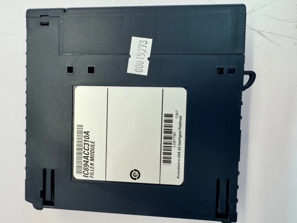
GE IC694ACC310
Field Service Pitfalls: What Rookies Get Wrong
Forcing Mismatched ConnectorsTechs try to plug ACC310 into wrong generation CPUs or backplanes—IC693 vs IC697 series. The connectors look similar but have different pin counts and keying. Forcing it damages pins, destroys the cable connector, and can short the CPU or backplane.
Field Rule: Verify part number matches both CPU and backplane series. ACC310 is for RX7i (IC697) and 90-70 CPUs—not for 90-30 systems (different cable). If connectors don’t mate smoothly, 终止—don’t force it. Check CPU part number and backplane compatibility before installing.
Bending Radius ViolationsTechs route the 1.5-meter cable around sharp cabinet corners or pinch it in cable ties. The minimum bend radius for parallel cables is 4-5 times the cable diameter. Sharp bends damage internal twisted pairs, cause signal crosstalk, or break conductors—resulting in intermittent CPU-backplane failures.
Quick Fix: Use proper cable management with smooth bends. Minimum bend radius for is approximately 1 inch (2.5 cm). Don’t kink the cable around cabinet edges. If you must make a tight turn, use a cable bend protector or route around larger radius. Signal integrity depends on maintaining conductor geometry.
Shield Grounding at Both EndsTechs connect the cable shield drain wire to ground at both CPU and backplane ends. This creates a ground loop—the shield carries ground current between different ground potentials, inducing noise into signal conductors. You get random CPU faults, I/O errors, or complete system crashes.
Field Rule: Connect the shield drain wire to chassis ground at one end only—typically at the backplane or CPU end, not both. If both ends share the same ground reference (single cabinet), grounding at both ends is acceptable. For multi-cabinet installations with separate ground systems, ground at one end to avoid ground loops.
Techs assume “GE parallel cable means universal” and try to use in Series 90-30 systems. Wrong. 90-30 systems use different parallel cables (IC693 series). The connectors physically won’t mate, or if forced, pinouts don’t match—damaging both cable and equipment.
Quick Fix: Verify your system series before ordering cables. is for RX7i/90-70 only (IC697 series CPUs). 90-30 systems (IC693 CPUs) require different cable assemblies with different connectors and pinouts. Check CPU part number first four digits: IC697 = , IC693 = different cable.
Cable Tie CompressionTechs over-tighten cable ties, compressing the jacket and internal twisted pairs. Compression damages conductor insulation, causes crosstalk between parallel lines, and can break signal conductors. The result: intermittent communication, random CPU resets, or I/O module faults.
Field Rule: Use cable ties with appropriate tension—not too tight. The rule of thumb: you should be able to slide a finger under the tie without force. Don’t compress the cable jacket visibly. Consider Velcro ties for parallel cables—they’re gentler and reusable. Over-tightening is a common rookie mistake that causes mysterious intermittent faults.
Routing Near High-Power CablesTechs route parallel cable directly next to 480VAC motor cables or VFD output cables. The magnetic fields from high-current power cables induce noise into the low-voltage parallel signals—even with shielding, you get data corruption.
Quick Fix: Maintain minimum 6-inch separation between and power cables. If you must cross power cables, do so at 90 degrees, not parallel runs. The EMI from VFD outputs is especially nasty—keep parallel data cables at least 12 inches from VFD output conductors if possible. Shielding helps, but distance is your best protection.
Connector Pin Damage During InstallationTechs align connectors by sight and push without feeling pin engagement. Misalignment bends pins on the CPU or backplane connector. A single bent pin kills the entire parallel bus—system won’t boot, and you’ve damaged expensive equipment.
Field Rule: Align connectors carefully by feel, not just sight. You should feel pins slide into sockets smoothly. If you feel resistance, 终止 and realign. Don’t rock or wiggle the connector to force it—this breaks pins. Inspect pins on both cable and equipment before installation if the cable looks used or previously mishandled.
Cable Length Exceeding SpecTechs chain multiple cables or use splices to extend beyond 1.5 meters. Each connection or splice adds impedance mismatch, signal reflection, and potential failure points. The cable is specified for 1.5 meters—going longer risks signal timing violations.
Field Rule: Don’t splice or daisy-chain parallel cables. If 1.5 meters isn’t enough, you need a different solution—relocate CPU or backplane, or use a different architecture with longer cable support. Each splice is a failure point, and signal degradation accumulates with length beyond spec.
Oil and Chemical ContaminationTechs install in oil-lubricated environments (gearboxes, hydraulic systems) without using oil-resistant cable variants. Standard PVC jacket absorbs oil, swells, cracks, and eventually fails. Industrial oil exposure destroys standard cables within months.
Quick Fix: For oily environments, specify oil-resistant jacket material (thermoplastic elastomer or nitrile). Standard PVC cables won’t survive continuous oil exposure. If oil contamination is possible, choose the right cable variant upfront—replacement in six months costs more than the premium for oil-resistant cable.
Connector Backshell GroundingTechs mount the cable connector without securing the backshell or ground strap to chassis. The connector relies on backshell contact for shield continuity. Without proper backshell grounding, the shield is disconnected at that end—EMI protection fails.
Field Rule: Secure connector backshells to chassis using mounting hardware provided. Ensure metal-to-metal contact for shield grounding. Don’t leave connectors floating—the shield won’t work without chassis contact. Test continuity between shield drain wire and chassis ground after installation.
Commercial Availability & Pricing Note
Please note: The listed price is for reference only and is not binding. Final pricing and terms are subject to negotiation based on current market conditions and availability.


