
Description
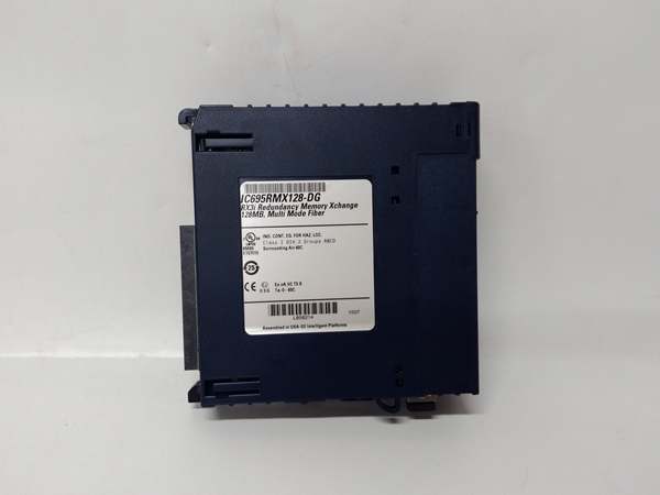
Hard-Numbers: Technical Specifications
- Communication Protocol: Genius Bus (GE Fanuc proprietary)
- Supported Media: Fiber optic (multimode, 62.5/125µm) or copper (shielded twisted pair)
- Fiber Optic Range: Up to 2000 meters (multimode)
- Copper Range: Up to 600 meters (shielded twisted pair)
- Communication Speed: 153.6 Kbps (Genius Bus standard)
- Baseplate Compatibility: Series 90-30 IC693 chassis (10-slot or 16-slot)
- Slot Position: Any slot except leftmost (power supply slot)
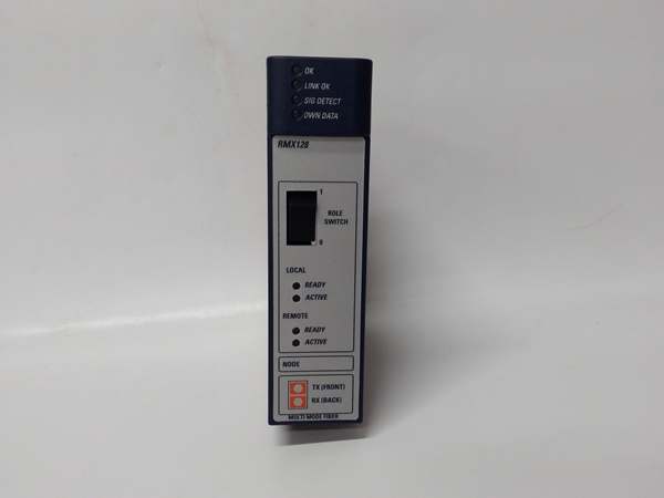
- LED Indicators: PWR (power), OK (module healthy), COM (communication active), ERR (fault)
- Isolation: 1500V optical isolation between bus and logic
- Operating Temperature: 0-60°C
- Power Draw: 500mA @ +5VDC from backplane
- Termination: Built-in bus termination switch (enabled on last module only)
- Addressing: DIP switches for bus address (1-32 per bus segment)
- Max Devices per Bus: 32 nodes (including master and remotes)
- Certifications: CE compliant, cULus listed
GE IC693RMX128
The Real-World Problem It Solves
PLC systems with massive physical footprints—steel rolling mills, paper machines, automotive assembly lines—hit the 15-meter cable length limit for standard I/O wiring. The RMX128 lets you locate I/O racks where the action is instead of running thousands of feet of individual field wires back to a central cabinet. Distributed I/O architecture reduces field wiring by 70-80%, cuts installation labor, and eliminates voltage drop issues on long analog signal runs.
Where you’ll typically find it:
- Steel Rolling Mills: Control cabinets at process lines spread over 1000+ feet. RMX128 allows remote I/O racks near rolling stands instead of running massive wire bundles from a central control room.
- Paper Machines: Distributed I/O at dryer sections, calender stacks, and reel stands. Fiber optic RMX128 runs eliminate EMI from variable frequency drives that would corrupt copper signals.
- Automotive Assembly Lines: Remote I/O islands at welding robots, paint booths, and assembly stations. Copper RMX128 connections cost less than fiber for moderate distances (under 600 meters).
Bottom line: RMX128 enables distributed I/O architecture for Series 90-30 systems where physical layout demands remote I/O placement. Use fiber optic for distances over 600 feet or high-EMI environments. Use copper for shorter runs where cost is critical. Either way, you eliminate massive field wire bundles and gain installation flexibility.
Hardware Architecture & Under-the-Hood Logic
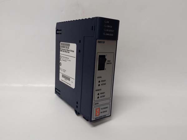
The RMX128 sits in any standard Series 90-30 slot (except leftmost power supply slot) and interfaces the CPU baseplate with remote baseplates via the Genius Bus. It doesn’t execute control logic—its job is transparent communication between CPU and remote I/O modules. Local and remote baseplates communicate as if all modules were in the same physical rack, with the handling the bus protocol, error detection, and data routing.
Internal signal flow and processing logic:
- Backplane interface: connects to the local 90-30 backplane via standard edge connector. It appears to the CPU as just another I/O module—no special programming required. The CPU reads/writes remote I/O data through using standard I/O instructions.
- Genius Bus controller: Onboard microcontroller manages Genius Bus protocol (token-passing, error checking, collision avoidance). DIP switches set bus address (1-32)—ensure each node has unique address on same segment. The controller handles bus arbitration and data packet routing transparently.
- Media interface: Physical layer depends on media type. For fiber optic, onboard transceiver converts electrical signals to optical via ST or SC connectors. For copper, differential drivers/receivers interface with shielded twisted pair (typically BNC or terminal block connections). Internal termination switch must be enabled only on the last physical device in the bus segment.
- Data buffering: Dual-port RAM buffers incoming/outgoing data between backplane and Genius Bus. Local CPU accesses remote I/O data with minimal latency (typically 5-10ms scan time addition). Buffer depth handles brief communication interruptions without faulting the CPU.
- Diagnostic monitoring: Onboard watchdog timer monitors communication health. If bus communication fails for longer than configured timeout (typically 3-5 seconds), the ERR LED illuminates and the CPU receives fault indication. Front LEDs provide instant status: PWR (module powered), OK (healthy), COM (bus traffic active), ERR (fault condition).
GE IC693RMX128
Field Service Pitfalls: What Rookies Get Wrong
Bus Termination Confusion
Techs enable termination on every “to be safe.” Wrong. Genius Bus requires termination only on the two physical ends of the bus segment. Multiple terminations cause signal reflections and communication failures—entire distributed system goes down randomly.
Field Rule: Enable termination switch only on the first and last physical devices in the bus segment. Verify with bus topology diagram. If you’re adding a new node in the middle, leave termination disabled. Multiple terminations cause reflection problems that are intermittent and difficult to troubleshoot.
Copper vs Fiber Distance Violation
Techs run copper connections 1200 feet because copper is cheaper than fiber. The spec limit is 600 meters maximum. Beyond that, signal degradation causes intermittent communication faults—random I/O failures that look like module problems but are actually bus communication issues.
Quick Fix: Measure cable run length before installation. Under 600 meters, copper works fine with shielded twisted pair. Over 600 feet, use fiber optic—cost difference is minor compared to troubleshooting downtime. Don’t push copper beyond spec—you’ll pay for it in random faults.
EMI in Copper Installations
Copper runs near high-power VFDs, welding equipment, or motor starters. The EMI corrupts Genius Bus signals, causing intermittent communication faults. Techs blame “bad modules” when the real issue is cable routing without proper shielding and separation.
Field Rule: Route copper cables at least 18 inches from power cables, VFD outputs, or welding leads. Use shielded twisted pair with drain wire properly grounded at one end only (typically at the CPU end). If you must cross power cables, do so at 90 degrees. In high-EMI environments, fiber optic eliminates the problem entirely.
Duplicate Bus Addresses
Techs replace an and set DIP switches to match the old module without checking other nodes. Duplicate addresses on the same bus segment cause bus collisions—communication fails for the entire segment, not just the duplicate node. The whole distributed system goes offline.
Quick Fix: Before installing a replacement , verify no other node on the bus uses the same address. Temporarily set new module to unused address, then power up and check bus health. If no conflicts, you can reassign addresses systematically. Document addresses—post-it notes fall off, causing this problem repeatedly.
Fiber Connector Contamination
Fiber optic ST or SC connectors get dirty in industrial environments—dust, oil, hydraulic fluid. Contaminated connectors cause signal loss, erratic communication, or complete bus failure. Techs clean connectors by blowing on them (bad idea—moisture contaminates fiber) or using dirty alcohol wipes.
Field Rule: Use proper fiber cleaning tools—dry fiber cleaner sticks or 99% isopropyl alcohol with lint-free wipes. Inspect connectors under magnification if possible. Never touch fiber end faces—skin oils cause permanent contamination. Keep protective dust caps on connectors when cables are disconnected.
Scan Time Impact on Control Loops
Techs add remote I/O to fast PID control loops (e.g., hydraulic positioning, web tension). The additional 5-10ms communication latency causes loop instability—oscillations, overshoot, poor performance. Techs blame “bad tuning” when the real issue is communication latency in the control loop.
Field Rule: Keep fast control loops (10ms scan or faster) on local I/O baseplate. Use for remote I/O with slower loops (50ms+ or discrete logic). If remote fast loops are unavoidable, increase PID derivative time and reduce proportional gain to compensate for added latency. Document which loops are remote—future techs won’t make the same tuning mistake.
Backplane Slot Power Limits
Techs fill remote baseplates with high-current I/O modules (analog outputs, specialty modules) without checking backplane power budget. The draws 500mA @ +5VDC, and each I/O module adds current draw. Overloading the remote backplate causes voltage sag—module erratic behavior, random faults, or complete failure.
Quick Fix: Calculate total +5VDC current draw on remote baseplates. The local power supply (PWR321/PWR331) provides +5VDC to both local and remote baseplates via the Genius Bus cable. Ensure total current from all baseplates doesn’t exceed power supply capacity. If over budget, add a local power supply at the remote rack or reduce module count.
Cold Startup Issues
Techs install systems in arctic applications without considering -40°C startup. Fiber optic transceivers and copper differential drivers have specified minimum operating temperatures. Below spec, modules won’t initialize—system fails to start until equipment warms up.
Field Rule: Check operating temperature range for your environment. Standard operates 0-60°C. For arctic applications (-40°C minimum), specify extended-temperature variants if available. If not, provide cabinet heating to maintain minimum temperature before startup. Don’t assume all electronics survive -40°C without verification.
Commercial Availability & Pricing Note
Please note: The listed price is for reference only and is not binding. Final pricing and terms are subject to negotiation based on current market conditions and availability.


