
Description
Hard-Numbers: Technical Specifications
- Input Voltage: 24 VDC nominal
- Input Voltage Range: 8-30 VDC (startup), 2-30 VDC (operating)
- Total Output Capacity: 30W maximum
- +5VDC Output: 5.0-5.2VDC (5.1VDC nominal), 30W max (6A @ 5VDC)
- +24VDC Relay Output: 24-28VDC, 5W max
- +24VDC Isolated Output: 21.5-28VDC, 20W max
- +5VDC Backplane Current: Approximately 6A maximum (double PWR321 capacity)
- Input Power: 50W DC at full load
- Inrush Current: 4A peak, 250ms maximum
- Holdup Time: 0 ms minimum (no bulk capacitor for holdup – DC input optimization)
- Overvoltage Protection: 6.4-7VDC on +5V rail
- Overcurrent Protection: 7A maximum on +5V rail
- Operating Temperature: 0-60°C
- Temperature Derating: Above 50°C, +5VDC current derates to 4.0A maximum at 60°C
- Mounting Location: Leftmost slot of baseplate only
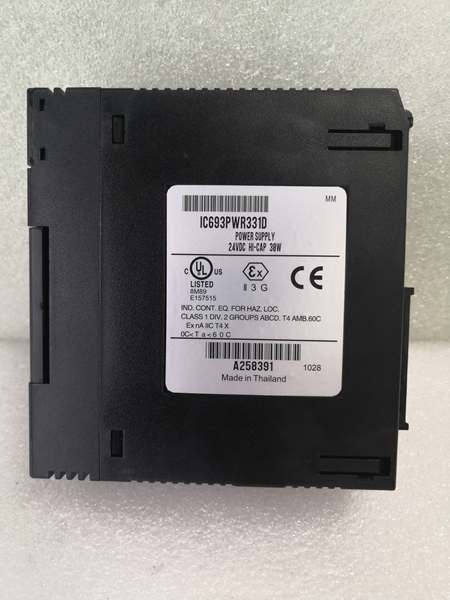
- Internal Fuse: GE catalog 44A724627-109 (field-replaceable)
- Certifications: CE compliant, cULus listed, Class I Division 2 rated
- Revision D Upgrades: Enhanced 105°C electrolytic capacitors (4000+ hours lifespan), 2oz copper pours on +5VDC traces, upgraded thermal interface materials between power semiconductors and heatsink
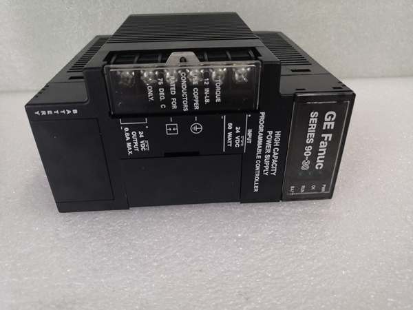
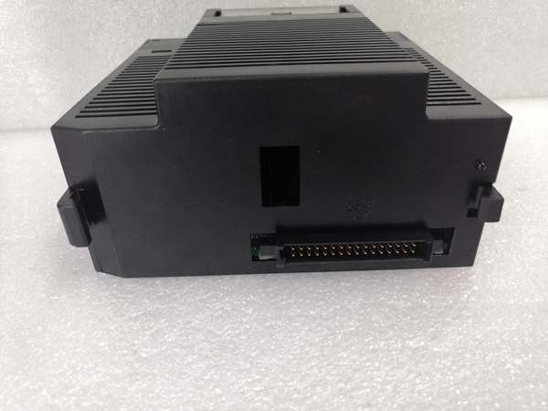
GE IC693PWR331
The Real-World Problem It Solves
The PWR331D solves the same core problem as the base PWR331—DC-powered systems with heavy +5VDC loads—but with Revision D’s component upgrades addressing premature failures in harsh, high-temperature environments. Early PWR331 revisions (A/B/C) could experience capacitor degradation in mobile equipment engine compartments or under-hood applications where ambient temperatures exceeded 50°C for extended periods. Revision D targets these failure points with extended-lifespan capacitors and improved thermal coupling.
The PWR331D advantage in three high-stress scenarios:
- Mining Haul Trucks and Earthmoving Equipment: These vehicles operate in environments where ambient temperatures reach 55-60°C under the hood, and vibration adds mechanical stress to solder joints and components. Revision D’s 4000+ hour capacitors (vs 2000-3000 hours in earlier revisions) and reinforced PCB traces with 2oz copper provide 2-3x longer lifespan in these conditions. The 30W +5VDC output powers dense sensor arrays—load cells, pressure transducers, position encoders—where PWR321 would require dual supplies.
- Solar-Powered Remote Installations in Hot Climates: Off-grid solar arrays in desert environments deliver 24VDC but experience extreme temperature swings (night -10°C, day +55°C). Revision D’s extended-temperature capacitors and enhanced thermal management maintain stable +5VDC output through these cycles. The DC-only design eliminates AC rectification losses, critical in solar applications where every watt of efficiency matters.
- Battery-Backup UPS Systems in Industrial Plants: Manufacturing facilities use battery-backed PLC systems to ride through power outages. These systems operate continuously at elevated cabinet temperatures (45-50°C) as batteries charge and discharge. Revision D’s improved thermal interface materials reduce switching transistor junction temperatures by 3-5°C compared to earlier revisions, significantly extending MTBF in continuous-duty applications.
Bottom line: PWR331D delivers the same 30W +5VDC capacity as base PWR331 but with Revision D’s component upgrades designed for harsh, high-temperature DC environments. If your application is mobile, solar-powered, or battery-backed with elevated ambient temperatures, Revision D’s extended lifespan justifies the investment. For mild-temperature indoor DC applications, base PWR331 may suffice.
Hardware Architecture & Under-the-Hood Logic
The PWR331D shares the same electrical architecture as base PWR331 (24VDC input, buck-boost pre-regulator, three isolated output rails), but Revision D introduces component-level upgrades targeting thermal performance and capacitor lifespan in high-temperature environments.
PWR331D vs earlier PWR331 revisions comparison:
| Component | Revision D (PWR331D) | Earlier Revisions (A/B/C) |
|---|---|---|
| Input Capacitors | 105°C rated, 4000+ hours | 85°C rated, 2000-3000 hours |
| +5VDC PCB Traces | 2oz copper, reinforced width | 1oz copper, standard width |
| Thermal Interface | High-performance phase-change pads | Standard thermal paste/pads |
| Switching Transistors | Lower thermal resistance package | Standard package |
| Output Capacitors | Low-ESR, 105°C rated | Standard ESR, 85°C rated |
Internal signal flow and Revision D enhancements:
- Input stage: 24VDC enters through enhanced EMI filter with upgraded ferrite cores for mobile equipment environments with high electrical noise from alternators and motor drives. Reverse polarity protection diode is upgraded to higher current rating (10A vs 5A in earlier revisions) to survive accidental reverse battery connections without damage. The buck-boost pre-regulator accepts 2-30VDC input and stabilizes voltage before the main switching stage.
- Primary switching: High-frequency DC-DC converter with upgraded MOSFETs featuring lower Rds(on) and improved thermal resistance (θjc reduced by 15%). Revision D uses phase-change thermal pads between switching transistors and heatsink, providing superior heat transfer compared to thermal paste used in earlier revisions. The result: switching junction temperatures run 3-5°C cooler at full 30W load—critical in 50-60°C ambient environments.
- Output isolation: Three separate secondary windings provide isolated rails. The +5VDC rail is the critical upgrade path: 2oz copper pours (vs 1oz in earlier revisions) reduce trace resistance, minimizing voltage drop under 6A full load. Output rectifier diodes are upgraded to lower forward voltage drop types (Schottky vs standard silicon), reducing diode conduction losses by 0.3-0.4V at 6A. Low-ESR output capacitors (105°C rated) maintain stable voltage despite high ripple current demands.
- Protection circuitry: Current limiters on each rail with faster response time (10µs) to prevent damage during transient overloads. Overcurrent threshold set to 7A on +5V rail—allows brief surge currents while protecting against sustained overload. Revision D includes enhanced voltage monitoring with tighter tolerance (±1% vs ±2% in earlier revisions) for earlier detection of voltage sag in high-load applications.
- Diagnostic monitoring: Voltage dividers feed into supervisory circuit driving front-panel LEDs (PWR, OK, FAULT). Revision D firmware includes enhanced temperature reporting—CPU can now read internal temperature via RS-485, enabling predictive maintenance before thermal shutdown. This diagnostic enhancement wasn’t available in earlier PWR331 revisions.
GE IC693PWR331
Field Service Pitfalls: What Rookies Get Wrong
Capacitor Replacement with Wrong Temperature RatingTechs replacing capacitors in Revision D modules substitute standard 85°C capacitors to save cost or because they’re more readily available. This defeats Revision D’s entire purpose—extended lifespan in high-temperature environments. The 85°C capacitors degrade rapidly in 50-60°C cabinets, failing within 6-12 months and causing “Revision D is no better than old revision” complaints.
Field Rule: When replacing capacitors in Revision D modules, always use 105°C rated capacitors with at least 4000-hour lifespan rating at 105°C. The voltage rating must match original (typically 16V or 25V for +5VDC rails). Low-ESR specification is critical for +5VDC output stability—don’t substitute general-purpose electrolytics.
Thermal Interface Material DegradationRevision D uses phase-change thermal pads between switching transistors and heatsink. Techs disassemble modules for capacitor replacement and reuse old thermal pads, assuming they’re still good. Phase-change material degrades after one disassembly cycle—reusing it creates thermal gaps, causing transistor overheating and premature failure.
Quick Fix: Replace thermal pads every time you disassemble the power stage. Use GE-specified replacement pads or equivalent high-performance phase-change material. Ensure surfaces are clean (isopropyl alcohol) before applying new pads. Don’t use standard thermal paste—it doesn’t fill gaps as effectively as phase-change material.
Voltage Drop Misdiagnosis in Revision DTechs assume Revision D’s reinforced PCB traces eliminate all voltage drop on the +5VDC rail. Under 6A full load, traces still drop 0.15-0.2V from supply to far end of backplane—that’s normal, not a defect. Techs replace “defective” Revision D modules when the real issue is undersized backplane wiring or corroded terminals.
Field Rule: Measure voltage at both the supply terminals and the farthest module. If the difference exceeds 0.3VDC, the problem is wiring resistance, not the supply. For backplanes longer than 12 inches or heavily loaded with multiple modules, use 18AWG or heavier wiring for the +5VDC rail. Revision D helps, but can’t fix external wiring issues.
Temperature Derating ConfusionTechs see Revision D’s enhanced thermal design and assume it eliminates temperature derating. At 60°C ambient, +5VDC current still derates to 4.0A maximum. Techs run full 6A load in 55°C+ environments and experience thermal shutdown, blaming “defective” modules when they’re exceeding derated specifications.
Quick Fix: Check the temperature derating curve before installation. At 50°C, capacity reduces to approximately 5A. At 60°C, it’s 4A maximum. If you need full 6A at elevated temperatures, add forced air cooling or relocate the module. Don’t assume “enhanced thermal design” means “no derating.”
Firmware Compatibility with Enhanced DiagnosticsRevision D includes internal temperature reporting via RS-485, but older CPU firmware versions (pre-v6.3) don’t recognize this diagnostic parameter. Techs install Revision D modules and see “unknown parameter” errors or communication failures in the programming software, assuming the module is incompatible.
Field Rule: Update CPU firmware to v6.3 or later before installing Revision D modules if you want to access enhanced diagnostics. If CPU upgrade isn’t feasible, Revision D still functions as a drop-in replacement—you just won’t see temperature reporting. The basic voltage and status diagnostics remain compatible with all CPU versions.
Reverse Polarity Protection LimitsRevision D includes enhanced reverse polarity protection (10A diode vs 5A in earlier revisions), but techs test it by connecting car batteries in reverse for extended periods. The protection diode survives the initial surge but overheats during sustained reverse polarity, eventually failing. Techs see blown protection components and assume the module is “defective.”
Field Rule: Reverse polarity protection is for accidental brief exposure, not sustained reverse voltage. If you accidentally connect in reverse, disconnect immediately—don’t leave it connected “to see what happens.” The 10A diode is rated for brief surge current, not continuous conduction in reverse.
Capacitor ESR Measurement ErrorsTechs use standard ESR meters to test Revision D’s low-ESR output capacitors and get readings that seem “too high” compared to general-purpose capacitors. Low-ESR capacitors have different ESR characteristics—standard meters aren’t calibrated for them, leading techs to replace good capacitors unnecessarily.
Field Rule: Low-ESR capacitors typically measure 0.02-0.05Ω ESR at 20°C using proper ESR meters with 100kHz test frequency. If your meter shows 0.1Ω or higher, verify the meter is designed for low-ESR capacitor testing. Don’t replace capacitors based on questionable ESR measurements—capacitance value and leakage current are more reliable indicators of capacitor health.
Commercial Availability & Pricing Note
Please note: The listed price is for reference only and is not binding. Final pricing and terms are subject to negotiation based on current market conditions and availability.


