
Description
Hard-Numbers: Technical Specifications
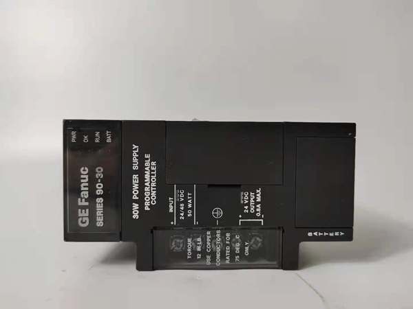
- Input Voltage: 120/240 VAC or 125 VDC nominal
- AC Input Range: 85-264 VAC (50/60Hz)
- DC Input Range: 100-300 VDC
- Total Output Capacity: 100W maximum (vs 30W on PWR321)
- +5VDC Output: 5.0-5.2VDC (5.1VDC nominal), 40W max (vs 15W on PWR321)
- +24VDC Relay Output: 24-28VDC, 30W max (vs 15W on PWR321)
- +24VDC Isolated Output: 21.5-28VDC, 40W max (vs 20W on PWR321)
- +5VDC Backplane Current: Approximately 8A maximum (vs 3A on PWR321)
- Input Power: 120VA (AC) / 70W (DC) at full load
- Inrush Current: 10A peak, 250ms maximum (higher than PWR321 due to larger input capacitor bank)
- Holdup Time: 20ms minimum
- Overvoltage Protection: 6.4-7VDC on +5V rail
- Overcurrent Protection: 8A maximum on +5V rail (vs 4A on )
- Communication: RS-485 serial port (9-pin sub-D connector)
- Operating Temperature: 0-60°C
- Mounting Location: Leftmost slot of baseplate only
- Internal Fuse: GE catalog 44A724627-109 or higher-rated equivalent (check revision-specific fuse rating)
- Certifications: CE compliant, cULus listed, Class I Division 2 rated
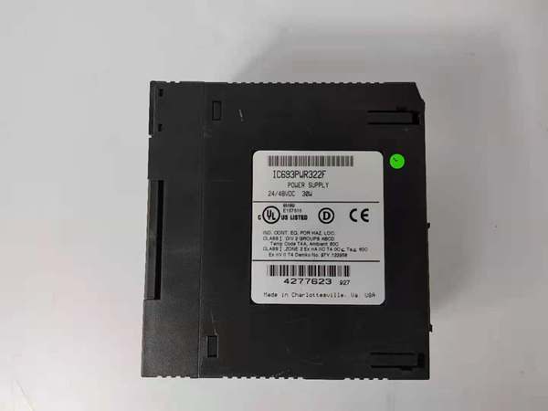
GE IC693PWR322
The Real-World Problem It Solves
The PWR322 eliminates the need for dual power supplies in heavily loaded racks where ‘s 30W limit causes chronic brownouts or forces you to split systems across multiple baseplates. When you’ve got a rack packed with analog modules (each drawing 150-200mA), communication modules (100-150mA each), and coprocessors (300-500mA), the ‘s 3A +5VDC rail hits its ceiling fast. PWR322 gives you 8A on the +5V rail and triple the total output capacity—critical for single-rack process control skids, E-trip cabinets, or HMI-heavy systems where module count and current draw would otherwise require redundant supplies.
Where you’ll typically find it:
- Chemical process unit control cabinets with 8-10 analog I/O modules plus multiple communication cards
- Turbine control panels with coprocessors, high-speed counter modules, and redundant CPU configurations
- DCS integration racks where multiple serial communication modules (CCM, SNP, Modbus) run simultaneously
Bottom line: PWR322 is the heavy-hitter supply for when your rack outgrows the standard 30W brick and you don’t want to redesign the cabinet or split into multiple baseplates.
Hardware Architecture & Under-the-Hood Logic
The PWR322 shares the same fundamental architecture as —AC/DC input, EMI filtering, bridge rectification, high-frequency switching—but scaled up for 100W output. The critical difference is in the power train: larger transformer, beefier output rectifiers, and higher-rated semiconductors to handle sustained 8A +5VDC current. The protection circuits are similarly scaled—current limiters trip at 8A instead of 4A, overvoltage crowbar fires at the same 6.4V threshold but with higher-energy handling capability.
Internal signal flow and protection logic:
- Input stage: AC/DC enters through a beefier EMI filter and bridge rectifier designed for higher continuous current. The bulk capacitor bank is larger to provide the same 20ms holdup time at 100W load—this is why inrush current hits 10A peak instead of 4A.
- Primary switching: Higher-power DC-DC converter generates intermediate bus voltage with pulse-width modulation. Efficiency drops slightly at higher loads (82-85% typical vs 85% on ), so expect more heat generation—ventilation matters in packed cabinets.
- Output isolation: Three separate secondary windings create isolated rails with higher current capability. The +5VDC rail uses thicker conductors and larger filter capacitors to handle 8A continuous without sagging under load transients.
- Protection circuitry: Current limiters on each rail are scaled to the higher ratings—8A for +5VDC, approximately 1.25A for each 24VDC rail. Short-circuit protection still crowbars the affected rail instantly while leaving others operational.
- Diagnostic monitoring: Same supervisory circuit architecture as , driving front-panel LEDs and RS-485 status registers. The overvoltage crowbar remains the same 6.4V threshold, but higher fault current capability means internal fuse must be rated accordingly—verify revision-specific fuse catalog number before replacement.
GE IC693PWR322
Field Service Pitfalls: What Rookies Get Wrong
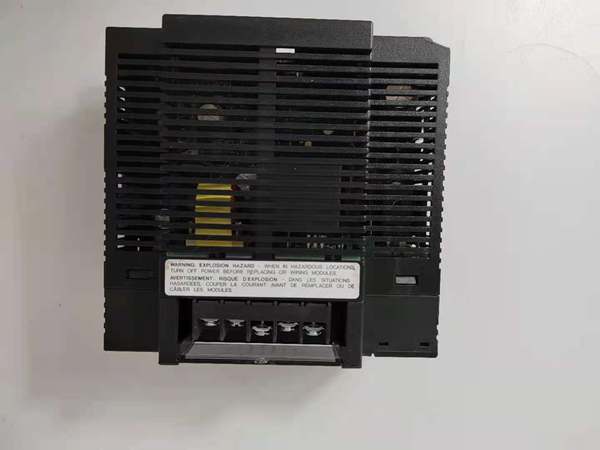
Inrush Current MisunderstandingPWR322 pulls 10A peak inrush vs 4A on . Techs replace a with PWR322 without checking upstream circuit protection and wonder why breakers trip during power-up. That bigger capacitor bank needs more headroom on your branch circuit protection.
Field Rule: Verify your upstream breaker or fuse can handle 10A inrush without nuisance trips. If you’re marginal on the existing installation, add a soft-start module or upgrade branch protection before swapping in . Don’t blame the module—your upstream protection was undersized for the higher load.
Heat Dissipation in Packed Cabinets100W output means more heat—simple thermodynamics. Techs shove into cabinets already running hot from multiple drives or PLCs, then scratch their heads when the supply overheats and shuts down. The needs airflow, especially if you’re running near full 40W +5VDC load.
Quick Fix: Calculate cabinet heat load before installing . If you’re pushing 80W+ output, add forced ventilation or relocate the module away from other heat sources. The operating temperature range is 0-60°C, but derate above 50°C for long-term reliability—those capacitors don’t like sustained high temps.
Fuse Rating Confusion might use a different internal fuse rating than due to higher current capability. Techs blindly install the GE 44A724627-109 fuse ( spec) and wonder why it blows prematurely or doesn’t protect adequately. Later revisions of use higher-rated fuses—check your specific revision’s documentation.
Field Rule: Consult the fuse catalog number printed on your specific revision’s internal fuse holder before replacement. Don’t assume fuse ratings carry over—wrong fuse means either nuisance trips or inadequate protection during real faults. Verify the exact catalog number and match it.
Backplane Current OverconfidenceJust because delivers 8A +5VDC doesn’t mean you can load it to 100% continuously. I’ve seen techs pack racks with 15+ high-current modules, thinking the supply can handle anything, then encounter intermittent shutdowns during heavy communication loads or simultaneous solenoid actuation.
Quick Fix: Derate to 80% of rated capacity (6.4A continuous on +5VDC) for reliable operation. Calculate worst-case module current draw including surge currents—coprocessors can draw 500mA+ during data transfer bursts. If you’re consistently above 6A, consider a second or split your system across multiple baseplates.
Terminal Block Compatibility typically uses a 6-terminal block like later revisions, but verify the exact terminal configuration before swapping from . Early revisions might have different screw spacing or terminal assignments than you expect.
Field Rule: Remove the terminal block from your old and compare it directly to the block. If screw spacing or terminal labels don’t match, don’t force it—rewire according to the documentation. Terminal block swaps are easy to mess up—get it right before applying power.
Module Mixing MadnessTechs mix and in the same baseplate, expecting them to share load. Bad idea—each supply independently powers the backplane, and output voltage variations between modules cause unequal current sharing or circulating currents.
Field Rule: Don’t mix supply types in the same baseplate unless you’re intentionally building a redundant supply architecture with diode isolation. For standard operation, use identical power supply models and revisions to ensure balanced backplane voltage distribution. Mixing creates more problems than it solves.
Commercial Availability & Pricing Note
Please note: The listed price is for reference only and is not binding. Final pricing and terms are subject to negotiation based on current market conditions and availability.


