
Description
Hard-Numbers: Technical Specifications
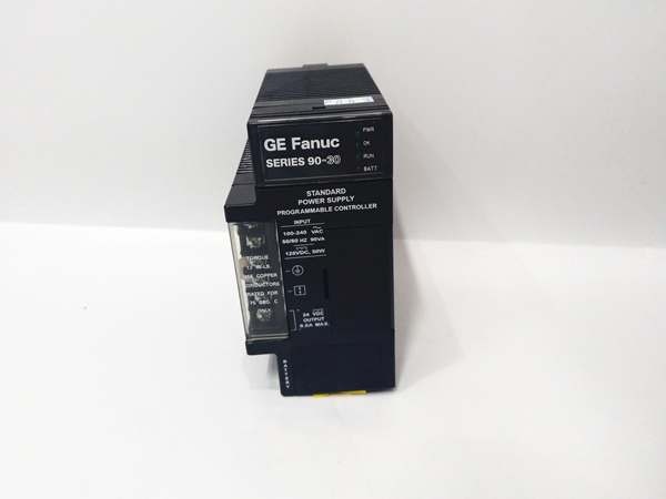
- Input Voltage: 120/240 VAC or 125 VDC nominal
- AC Input Range: 85-264 VAC (50/60Hz)
- DC Input Range: 100-300 VDC
- Total Output Capacity: 30W maximum
- +5VDC Output: 5.0-5.2VDC (5.1VDC nominal), 15W max
- +24VDC Relay Output: 24-28VDC, 15W max
- +24VDC Isolated Output: 21.5-28VDC, 20W max
- Input Power: 90VA (AC) / 50W (DC) at full load
- Inrush Current: 4A peak, 250ms maximum
- Holdup Time: 20ms minimum
- Overvoltage Protection: 6.4-7VDC on +5V rail
- Overcurrent Protection: 4A maximum on +5V rail
- Communication: RS-485 serial port (9-pin sub-D connector)
- Operating Temperature: 0-60°C
- Mounting Location: Leftmost slot of baseplate only
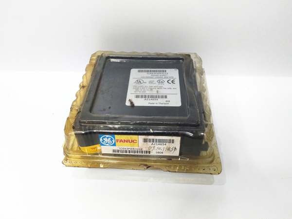
- Internal Fuse: GE catalog 44A724627-109 (field-replaceable)
- Certifications: CE compliant, cULus listed, Class I Division 2 rated
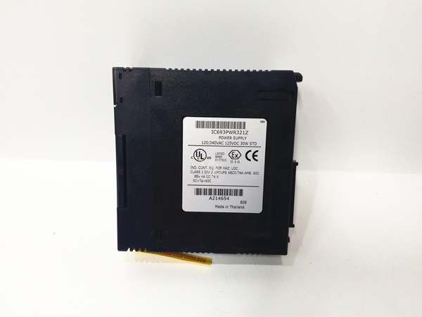
IC693PWR321
The Real-World Problem It Solves
The IC693PWR321Y solves the cabinet-space constraint in retrofits where you need both AC grid power and DC backup capability without swapping power supplies. This module gives you a single 30W brick that handles either input type while delivering isolated 24V for field devices and relay 24V for output modules—critical when you’re squeezing upgrades into existing enclosures and can’t add external power bricks.
Where you’ll typically find it:
- Paper mill drives cabinets where AC mains power the PLC but DC backup buses exist for critical control loops
- Offshore platform control systems requiring 24VDC input from UPS for redundant operation
- Steel mill E-trip cabinets needing isolated 24V for transmitter excitation without ground loops
Bottom line: One module covers both input scenarios while giving you three clean, protected rails for distribution across your rack.
Hardware Architecture & Under-the-Hood Logic
The PWR321Y is a passive supply with smart protection circuits—no microprocessor here, just solid-state regulation and monitoring. It converts incoming AC/DC to three isolated DC rails through high-frequency switching, with each output having its own current limiting and overvoltage shutdown circuitry. The RS-485 port enables external monitoring of supply status for HMI integration, but the core power train is analog for fast response and reliability.
Internal signal flow and protection logic:
- Input stage: AC/DC enters through a common EMI filter and bridge rectifier, feeding a bulk capacitor that provides 20ms holdup time during voltage sags.
- Primary switching: High-frequency DC-DC converter generates intermediate bus voltage with pulse-width modulation for regulation—this is where efficiency losses happen (85% typical), so expect heat at full 30W load.
- Output isolation: Three separate secondary windings (or transformer taps) create isolated rails: +5VDC for backplane, +24VDC relay for output modules, +24VDC isolated for field devices. Each rail has its own rectifier, filter capacitor, and linear regulator stage.
- Protection circuitry: Current limiters on each rail sense output current via sense resistors—when you hit 110% of rated load, the PWM throttles back. If short circuit occurs, protection crowbar fires, shutting down that rail instantly while leaving other rails alive.
- Diagnostic monitoring: Voltage dividers feed into a supervisory circuit that drives front-panel LEDs and RS-485 status registers. If overvoltage triggers on +5V (above 6.4V), the crowbar shorts** output to ground and blows the internal fuse, taking the whole module offline to protect downstream components.
IC693PWR321
Field Service Pitfalls: What Rookies Get Wrong
Terminal Block Upgrade ConfusionEarlier PWR321 revisions (A through S) had 5-terminal blocks. Revision Y has 6 terminals. If you’re replacing an older revision, existing wiring might not line up because the new terminal arrangement provides dedicated points for each output rail. I’ve seen techs jamming wires into wrong positions, causing backplane brownouts.
Field Rule: Check your terminal block screw count before removing the old module. Rev Y will have 6 screws—verify your existing wiring diagram maps to the new block layout. The terminal block is removable—swap it if you’re retrofitting and want to preserve wire connections.
Fuse Sizing MadnessThe internal fuse is rated specifically for inrush current handling and fault coordination. Techs throw in whatever 2A glass fuse fits, bypassing the coordination. Wrong fuse rating means the supply dies before external protection trips, or worse—doesn’t trip at all during a fault and cooks the downstream modules.
Quick Fix: Use only GE catalog 44A724627-109. Third-party equivalents exist (Bussman 215-002/GDC-2 or Littlefuse 239-002), but verify the exact current rating and time-delay curve. Never exceed the specified rating—those 4A inrush spikes will blow fast-acting fuses during power-up.
Isolated Output Grounding ErrorsThat isolated 24V rail exists for a reason—prevent ground loops. I still find techs tying the isolated 24V COM to chassis ground “for safety,” which kills the isolation and defeats the purpose of running separate sensors. Next thing you know, noise on your analog inputs and weird sensor readings.
Field Rule: The isolated 24V COM stays floating. Connect your sensor returns to this COM only, not to chassis. If you need safety grounding, use a single-point ground reference at the sensor end, not at the PLC supply. The isolation is your insurance against VFD noise.
Slot Placement IgnoranceThis supply goes in the leftmost slot—period. I’ve seen junior engineers jamming it into middle slots when upgrading, thinking “it’s just a power supply.” The backplane power distribution traces start at slot 1—installing it elsewhere means your modules upstream get no power or noisy, unregulated power through shared traces.
Quick Fix: Leftmost slot only. If your baseplate has something else there (maybe a CPU in an old system), you’re using the wrong baseplate type or power supply model. PWR321 requires the power slot—don’t force fit it elsewhere or you’ll damage the backplane power traces.
Revision Y Firmware NuancesRevision Y includes minor firmware updates to the diagnostic circuitry compared to earlier revisions (U, W, X). The RS-485 status registers might report slightly different error codes or thresholds. If you’re swapping in a Rev Y and your HMI shows unexpected “supply fault” messages, your PLC code might be hard-coded to expect older revision behavior.
Field Rule: Check your PLC alarm handling logic after any power supply revision change. Rev Y’s diagnostic thresholds are tighter on voltage sag detection—your existing alarm delays might be too short, causing nuisance trips during brief inrush events. Adjust your alarm timers if needed, but don’t disable the protection.
Commercial Availability & Pricing Note
Please note: The listed price is for reference only and is not binding. Final pricing and terms are subject to negotiation based on current market conditions and availability.


