
Description
System Architecture & Operational Principle
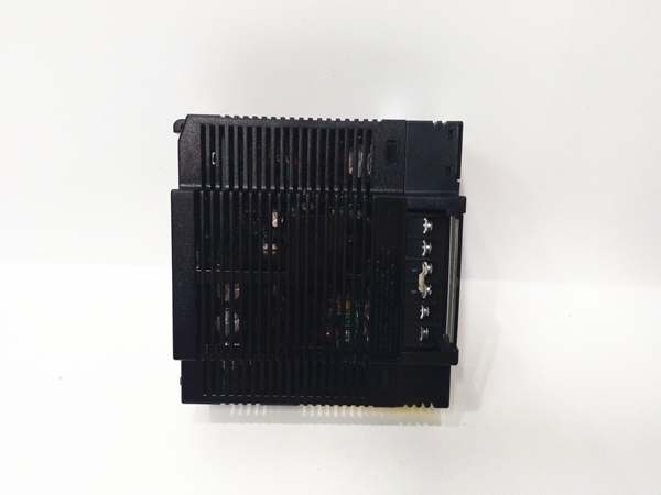
The IC693PWR321 is a DC input power supply module designed for GE 90-30 PLC systems that operate from 24VDC sources rather than AC line voltage. It occupies a single slot in any baseplate (CPU baseplate, expansion baseplate, or remote baseplate) and converts 24VDC input voltage to regulated DC outputs for the PLC system. This module is specifically engineered for applications where AC power is unavailable (remote locations, mobile equipment) or where DC power distribution is preferred (solar installations, battery backup systems, 24VDC bus architectures).
Wide-Range DC Input Voltage
The PWR321 accepts a wide DC input voltage range of 18VDC to 30VDC, making it compatible with standard 24VDC industrial power systems, battery systems (typically 12V or 24V lead-acid battery banks), and solar panel outputs with MPPT controllers. The wide input range accommodates battery voltage variations during discharge (down to 18VDC) and charging (up to 30VDC for 24V lead-acid systems), ensuring continuous operation throughout the battery’s charge cycle. This flexibility eliminates the need for external voltage regulators between the DC source and the power supply, simplifying system design and reducing component count.
DC-to-DC Conversion Architecture
Unlike AC input power supplies (e.g., PTM101A) that use transformer-based AC-to-DC conversion, the PWR321 employs high-frequency switching DC-to-DC converter technology. This architecture provides several advantages:
- High Efficiency: Typical efficiency of 85% reduces heat generation and minimizes battery drain, extending battery runtime in mobile or solar applications.
- Compact Size: Switching converters are smaller and lighter than transformer-based designs, reducing module weight and heat generation.
- Fast Response: High-frequency switching enables rapid response to load changes, maintaining stable output voltage during sudden current demand spikes (e.g., solenoid actuation).
- Wide Input Range Accommodation: Switching converters maintain regulation across wide input voltage ranges, ensuring stable output even as input voltage varies significantly.
The DC-to-DC converter topology is optimized for 24VDC input and 5VDC/15VDC output, with careful attention to minimizing electromagnetic interference (EMI) and conducted noise that could affect sensitive analog modules or communication circuits in the PLC system.
Dual DC Output Rails
The power supply generates two independent DC output rails:
- 5VDC Rail: Primary backplane power rail providing up to 20A (100W) to the PLC backplane. This high-current output capacity supports densely populated racks with multiple high-current modules such as analog I/O modules, communication modules, and coprocessors. The 20A rating is significantly higher than the 5A output of AC input power supplies like the PTM101A, enabling support for larger module complements without requiring multiple power supplies.
- 15VDC Rail: Auxiliary output rail providing up to 0.5A (7.5W) for specialized applications requiring 15VDC, such as certain analog transmitters, operator interface devices, or field instruments requiring 15VDC excitation. This output is isolated from both the 5VDC backplane rail and the DC input, providing noise immunity and preventing ground loops.
The two output rails are galvanically isolated from each other and from the DC input, providing noise immunity and preventing ground loops when external devices are powered from the auxiliary outputs. This isolation is particularly important in battery-powered applications where the DC source may have significant electrical noise from battery chargers, inverters, or other DC loads.
High-Efficiency Conversion for Battery-Powered Applications
The PWR321’s 85% typical efficiency is a critical advantage for battery-powered and solar-powered applications. At full load (100W output), the input current draw at 24VDC is approximately 4.9A (100W / 0.85 / 24VDC = 4.9A). This low input current draw minimizes battery drain and extends battery runtime. In a 24VDC lead-acid battery system with 100Ah capacity, the PWR321 at 50% load (50W output) draws approximately 2.45A from the battery, providing approximately 40 hours of runtime before the battery reaches 50% discharge depth. Compared to lower-efficiency power supplies (70% efficiency), the PWR321 provides approximately 21% longer battery runtime, significantly reducing operational costs and battery replacement frequency in remote applications.
Current Limiting and Short-Circuit Protection
Both DC output rails incorporate independent current limiting and short-circuit protection circuits:
- 5VDC Rail Protection: If the backplane current draw exceeds approximately 22A (110% of rated capacity), the current limiter reduces output voltage to limit current to approximately 22A. If a short circuit occurs, the protection circuit shuts down the 5VDC output completely to prevent damage to the power supply and backplane components. The protection circuit is designed with soft recovery to minimize output transients when the fault condition is removed.
- 15VDC Rail Protection: If the auxiliary current draw exceeds approximately 0.55A (110% of rated capacity), the current limiter reduces output voltage. If a short circuit occurs, the 15VDC output shuts down while the 5VDC backplane power remains operational.
The protection circuits are non-latching—once the overload or short circuit condition is removed, the power supply automatically restarts and resumes normal operation. This automatic recovery prevents production 终止pages in applications where momentary faults may occur (e.g., intermittent wiring issues with mobile equipment).
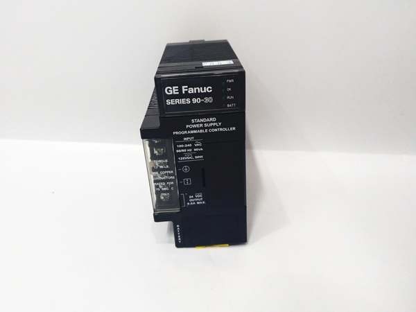
Diagnostic LED Indicators
The PWR321 includes two LED indicators on the front panel for status monitoring:
- PWR LED: Illuminates when DC input voltage is present and within the acceptable operating range (18-30VDC). If the PWR LED is OFF, check DC input wiring, battery/solar voltage, and the field-replaceable fuse.
- OK LED: Illuminates when both DC output rails (5VDC and 15VDC) are within specification and no protection circuits are active. If the OK LED is OFF while the PWR LED is ON, check for overloaded output rails, short circuits, or output wiring faults.
The LED indicators provide immediate visual feedback during startup and troubleshooting, enabling rapid identification of power-related issues without requiring external test equipment. In battery-powered applications, the PWR LED also provides quick indication of battery voltage status—dim illumination may indicate low battery voltage approaching the 18VDC minimum input threshold.
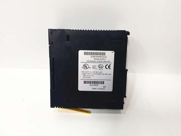
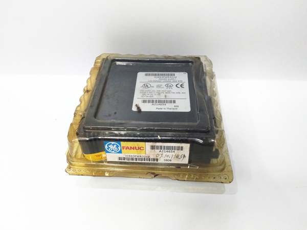
IC693PWR321
Core Technical Specifications
- Input Voltage: 18-30VDC nominal (designed for 24VDC systems)
- Input Voltage Range: 18VDC minimum to 30VDC maximum
- Input Current: Approximately 4.9A @ 24VDC at full load (100W output)
- Input Reverse Polarity Protection: Yes (prevents damage if input polarity is reversed)
- 5VDC Output: 5VDC ±5% @ 20A (100W) – Backplane power rail
- 15VDC Output: 15VDC ±5% @ 0.5A (7.5W) – Auxiliary power rail
- Total Output Capacity: Up to 107.5W (5VDC + 15VDC combined, limited by input capacity)
- Efficiency: 85% typical at full load
- Overcurrent Protection: Current limiting at approximately 110% of rated output
- Short-Circuit Protection: Auto-recovery shutdown on output short circuits
- Overvoltage Protection: Shutdown if input voltage exceeds 30VDC
- Undervoltage Protection: Shutdown if input voltage falls below 18VDC
- LED Indicators: PWR (input power present), OK (outputs within specification)
- Fuse Protection: Field-replaceable fuse (rating varies by input voltage application)
- Mounting Location: Any slot in any baseplate (CPU, expansion, or remote baseplate)
- Backplane Current Draw: Provides up to 20A @ 5VDC to backplane
- Auxiliary Current: Provides up to 0.5A @ 15VDC to external devices
- Operating Temperature: 0°C to 60°C
- Storage Temperature: -40°C to 85°C
- Humidity: 5% to 95% non-condensing
- Altitude: Up to 2000m (derate above 2000m)
- Dimensions: 80mm x 114mm x 54mm (H x W x D)
- Weight: Approximately 0.35kg
- Documentation: GFK-0255 (Series 90-30 Power Supply Modules User’s Manual)
Customer Value & Operational Benefits
DC Input Compatibility Enables Remote and Mobile Applications
The ‘s 18-30VDC DC input range enables PLC systems to operate from battery power, solar panels, or 24VDC bus systems without requiring AC inverters or external AC-to-DC converters. This capability is critical for remote locations where AC grid power is unavailable (oil/gas wellheads, mining equipment, agricultural irrigation systems, telecommunications sites) or mobile applications where DC power is the primary source (material handling vehicles, construction equipment, marine vessels). The wide input range accommodates battery voltage variations during charge/discharge cycles, ensuring continuous operation without requiring external voltage regulators or battery management systems.
High Backplane Current Capacity Supports Densely Populated Racks
The 20A @ 5VDC backplane output capacity is four times higher than standard AC input power supplies (PTM101A provides 5A @ 5VDC). This high current capacity supports densely populated racks with multiple high-current modules such as analog I/O modules (which typically draw 150-200mA per module), communication modules (which typically draw 100-150mA per module), and coprocessors (which typically draw 300-500mA per module). The can support racks with up to 20+ mixed I/O modules and multiple communication modules without requiring multiple power supplies, reducing hardware count, cabinet space requirements, and installation complexity. For applications requiring even higher backplane current, multiple modules can be installed in the same baseplate, providing up to 60A total backplane capacity (up to three modules).
High Efficiency Reduces Battery Drain and Operating Costs
The 85% typical efficiency minimizes power losses during DC-to-DC conversion, reducing battery drain and extending battery runtime in battery-powered applications. Compared to lower-efficiency power supplies (70% efficiency typical for older transformer-based designs), the provides approximately 21% longer battery runtime, reducing operational costs and battery replacement frequency. In a solar-powered application with limited solar panel capacity, the high efficiency reduces the required solar panel capacity and battery bank size, lowering system capital costs. For mobile applications powered by vehicle batteries, the reduced battery drain minimizes the risk of vehicle starting issues due to battery depletion during extended PLC operation.
Integrated 15VDC Auxiliary Output Reduces External Power Requirements
The 0.5A @ 15VDC auxiliary output provides convenient power for specialized field devices requiring 15VDC excitation, such as certain analog transmitters (e.g., 4-20mA transmitters with 15VDC excitation requirements), operator interface devices, or field instruments. This integrated 15VDC output eliminates the need for separate DC-to-DC converters or 15VDC power supplies, reducing hardware count, wiring complexity, and cabinet footprint. The isolation between the 15VDC rail and the 5VDC backplane rail prevents ground loops and noise coupling, improving system reliability in applications with sensitive analog measurements.
Wide Input Voltage Range Accommodates Battery Variations
The 18-30VDC input range accommodates significant battery voltage variations during charge/discharge cycles. In a 24VDC lead-acid battery system, voltage typically ranges from 21-24VDC during float/charge to 18-21VDC during discharge. The maintains stable output across this entire range, ensuring continuous PLC operation without requiring external voltage regulators or battery management systems. This wide input range also accommodates solar panel output variations due to changing sunlight conditions, MPPT controller operation, and temperature effects, ensuring reliable operation in solar-powered applications without requiring oversizing of solar arrays or battery banks.
IC693PWR321
Field Engineer’s Notes (From the Trenches)
Input voltage monitoring is critical in battery-powered applications. The operates from 18-30VDC, but battery voltage during discharge can fall below 18VDC if the battery is heavily loaded or deeply discharged. I’ve encountered solar-powered systems where battery voltage dropped to 15VDC during periods of high load and low sunlight, causing the to shut down due to undervoltage protection. Implement battery voltage monitoring with a high-voltage cutoff set at 19-20VDC to provide margin for the ‘s 18VDC minimum input threshold. This prevents deep discharge cycles that damage batteries and ensures the PLC has time for graceful shutdown before power loss. For critical applications, implement a low-voltage alarm that warns operators before battery voltage approaches the ‘s minimum input threshold.
The 20A backplane current capacity is frequently misinterpreted as “unlimited capacity.” While 20A is significantly higher than AC input power supplies, it’s still a finite limit that can be exceeded in densely populated racks. I’ve designed racks with 15+ mixed modules (including multiple analog I/O modules and communication modules) that appeared within the 20A limit but drew 22A during operation, causing intermittent shutdowns and OK LED flashing. Always calculate worst-case backplane current draw using manufacturer’s module specifications, then add 20% safety margin. If total backplane current exceeds 16A (80% of 20A capacity), consider installing a second in the same baseplate for redundancy and capacity. Remember that module current draw varies with operating mode—analog modules draw more current during active scanning, communication modules draw more current during high-speed data transfer.
The 15VDC auxiliary output is often misused or overlooked. I’ve encountered systems where technicians attempted to power solenoids or actuators from the 15VDC output, exceeding the 0.5A current limit and causing OK LED flashing. The 15VDC output is designed for low-power devices requiring 15VDC excitation, such as certain analog transmitters or specialized field instruments. For higher-power 24VDC devices, use external power supplies or connect them to the 24VDC source before the (with appropriate fuse protection). If you need a 15VDC supply for higher-current applications, use an external DC-to-DC converter rather than overloading the ‘s auxiliary output.
Reverse polarity protection prevents damage if input connections are swapped, but it doesn’t protect against all wiring errors. I’ve encountered installations where technicians connected the input to 24VAC instead of 24VDC, causing immediate catastrophic failure. The is designed for DC input only—AC input will damage the module. Always verify the input source type (DC vs. AC) with a multimeter before connecting to the . Label the input terminals “DC INPUT ONLY” to prevent future confusion. For facilities with both AC and DC distribution systems, use color-coded wiring (e.g., red/black for DC, brown/blue for AC) and polarized connectors to prevent accidental misconnection.
The PWR LED provides battery voltage indication, but its brightness varies with input voltage. At 30VDC input (fully charged battery or high solar output), the PWR LED is brightly illuminated. At 18VDC input (near minimum threshold), the PWR LED is dimly illuminated. This brightness variation can be misleading—technicians may assume the PWR LED is “dim” due to LED failure when the battery voltage is simply low. Use a multimeter to measure actual input voltage rather than relying solely on LED brightness. For critical applications, consider adding an external voltage indicator or battery monitor that provides quantitative voltage readings rather than qualitative LED brightness.
The 85% efficiency is typical at full load but decreases at lighter loads. At 50% load (50W output), efficiency is approximately 83%; at 25% load (25W output), efficiency is approximately 78%. This efficiency reduction at light loads is characteristic of switching power supplies and must be considered in battery runtime calculations. Don’t assume 85% efficiency for all operating conditions—calculate battery drain based on actual expected load rather than worst-case full load. For solar-powered applications with highly variable loads (e.g., daytime high load, nighttime low load), use average load for battery sizing calculations rather than peak load, accounting for the efficiency curve at various load points.
Solar-powered applications require careful sizing of solar panels and battery banks. The draws approximately 4.9A @ 24VDC at full load (100W output), but solar panel output varies with sunlight conditions, time of day, and temperature. I’ve encountered solar-powered systems where technicians sized the solar array for average load without accounting for periods of low sunlight (cloudy days, winter months), causing battery depletion and PLC shutdown during extended low-sunlight periods. Size solar panels for worst-case conditions (minimum sunlight hours for your geographic location) with 30-50% margin for cloudy days and panel degradation. Size battery banks for autonomy (number of days without sufficient sunlight) with 50% discharge depth limit to preserve battery life. Use MPPT solar charge controllers rather than PWM controllers for improved efficiency in variable sunlight conditions.
Battery-powered mobile applications require attention to vehicle starting considerations. The draws significant current from the vehicle battery (up to 4.9A at full load), which can reduce battery capacity available for engine starting. I’ve encountered forklift-mounted PLC systems where extended PLC operation caused battery depletion, resulting in failed engine starts at shift change. Calculate battery capacity requirements considering both PLC load and starting current reserve. For vehicles with limited battery capacity, implement automatic PLC shutdown when ignition is turned off, or use separate battery banks for PLC and vehicle starting systems. Install low-voltage cutoff relays to prevent deep discharge that damages batteries and ensures sufficient reserve capacity for engine starting.
Grounding and noise issues are particularly problematic in battery-powered and solar-powered applications. The DC source (battery bank or solar array) may have significant electrical noise from battery chargers, MPPT controllers, or other DC loads. This noise can couple through the and affect sensitive analog modules or communication circuits. Implement proper grounding practices—connect the DC negative to the PLC chassis ground at a single point to prevent ground loops. Install input filtering (e.g., line reactors or capacitors) between the DC source and the to reduce conducted noise. If you observe erratic analog readings or communication errors, suspect noise coupling before assuming module failure.
Real-World Applications
Oil/Gas Wellhead Remote Monitoring System
An oil and gas operator installed remote wellhead monitoring systems powered by solar panels and 24VDC battery banks. Each wellhead used a GE 90-30 PLC system with a DC input power supply, CPU350 module, four analog input modules (IC693ALG220), two communication modules (IC693CMM311 for local radio, IC693CMM321 for satellite), and various digital I/O modules. The solar array (two 100W panels) charged a 200Ah 24VDC battery bank via an MPPT charge controller. The ‘s high efficiency (85%) minimized battery drain, providing approximately 72 hours of autonomous operation during winter months with limited sunlight. The wide 18-30VDC input range accommodated battery voltage variations from 21VDC (during charge) to 18.5VDC (during discharge), ensuring continuous PLC operation. The 20A backplane current capacity supported all modules without requiring multiple power supplies, reducing hardware complexity in the compact wellhead enclosure.
Agricultural Irrigation Control System
A large-scale agricultural irrigation system used solar-powered PLC controllers at remote irrigation zones. Each zone controller included a GE 90-30 PLC system with a power supply, CPU351 module, six digital output modules (IC693MDL750 controlling solenoid valves), four digital input modules (IC693MDL740 for flow switches and pressure switches), and a radio communication module (IC693CMM311). The solar array (150W panel) charged a 100Ah 24VDC battery bank. The powered the PLC system for approximately 48 hours of autonomous operation during periods of low sunlight (cloudy days). The wide input voltage range accommodated battery voltage variations during solenoid actuation (which caused brief voltage dips), preventing PLC shutdown during valve operation. The ‘s current limiting protected the system during wiring faults—when a solenoid wiring short occurred, the 5VDC protection circuit activated, shutting down backplane power while protecting the battery from excessive current draw and preventing further damage.
Marine Vessel Propulsion Control System
A marine vessel’s propulsion control system used a GE 90-30 PLC system powered by the vessel’s 24VDC DC bus. The PLC system included a power supply, CPU352 module, eight analog input modules (IC693ALG220 for throttle position, engine temperature, oil pressure), four analog output modules (IC693ALG440 for governor control), and two communication modules (IC693CMM321 for VFD communication, IC693CMM311 for shipboard network). The vessel’s 24VDC DC bus was powered by two 24VDC alternators and a 200Ah battery bank for backup. The ‘s reverse polarity protection prevented damage if DC bus connections were reversed during maintenance. The high-efficiency conversion (85%) reduced load on the alternators, improving fuel efficiency and reducing heat generation in the engine room. The 20A backplane current capacity supported the high module count and multiple analog modules (which draw significant current), eliminating the need for multiple power supplies in the space-constrained engine room.
Material Handling Forklift Control System
A material handling facility’s automated forklift used a GE 90-30 PLC system powered by the forklift’s 24VDC traction battery. The PLC system included a power supply, CPU351 module, six digital input modules (IC693MDL740 for limit switches, bumper switches, and safety sensors), four digital output modules (IC693MDL750 for steering and lift actuators), two analog input modules (IC693ALG220 for battery voltage and current monitoring), and a radio communication module (IC693CMM311). The drew approximately 3A @ 24VDC from the traction battery during operation, reducing battery capacity available for traction. To ensure sufficient battery reserve for starting and operation, the facility implemented a 72VDC traction battery with a DC-to-DC converter providing 24VDC for the PLC system. The ‘s wide input voltage range accommodated the converted 24VDC, which varied between 22-26VDC depending on load and battery state of charge. The protection circuits protected the PLC system during battery voltage spikes during regenerative braking and voltage dips during high-current traction motor operation.
High-Frequency Troubleshooting FAQ
A: The requires a minimum input voltage of 18VDC and cannot operate directly from 12VDC battery systems. However, you can use a DC-to-DC boost converter (12VDC to 24VDC) between a 12VDC battery bank and the input. This approach is commonly used in automotive and marine applications where 12VDC batteries are standard. When using a boost converter, ensure the converter’s output current capacity exceeds the ‘s input current requirements (up to 4.9A at full load). Also consider the boost converter’s efficiency (typically 85-90%) in battery runtime calculations—the overall system efficiency becomes the product of boost converter efficiency and efficiency, reducing overall efficiency to approximately 72-77%.
Q: What causes the PWR LED to dim or flicker?
A: The PWR LED indicates DC input voltage is present, and its brightness varies with input voltage. Dim or flickering PWR LED indicates low input voltage approaching or falling below the 18VDC minimum threshold. Possible causes include:
- Battery discharge below 18VDC due to heavy load or insufficient charging
- Solar panel output insufficient due to low sunlight conditions or panel degradation
- Poor connections or voltage drops in input wiring due to undersized conductors or corroded terminals
- Input source (battery charger or DC bus) unable to maintain sufficient voltage under load
Measure the actual input voltage at the terminals with a multimeter. If voltage is below 18VDC, the will shut down. Address the root cause (recharge battery, increase solar capacity, reduce load, repair wiring) rather than ignoring the dim LED as a cosmetic issue.
A: Yes, multiple modules can be installed in the same baseplate, and the backplane current capacity becomes the sum of all installed power supplies (up to 60A with three modules). This is NOT parallel connection in the traditional sense—each module independently powers the backplane, and the total backplane current is distributed among modules based on their output voltage setpoints (typically within ±2% of each other). However, the 15VDC auxiliary outputs should NOT be connected in parallel—each ‘s 15VDC output should power separate auxiliary devices. Paralleling 15VDC outputs causes unequal current sharing and can lead to module overheating. For very high backplane current requirements (above 60A), consider using multiple baseplates with separate power supplies rather than installing more than three modules in a single baseplate.
A: Battery runtime calculation requires knowing the ‘s input current draw at expected load and the battery’s usable capacity. The ‘s input current draw (in amps) equals:
Input Current = Output Power / (Efficiency × Input Voltage)
For example, at 50% load (50W output) with 85% efficiency at 24VDC:Input Current = 50W / (0.85 × 24V) = 2.45A
For a 100Ah 24VDC battery with 50% discharge depth limit (50Ah usable):Runtime = Usable Capacity / Input Current = 50Ah / 2.45A = 20.4 hours
Always include safety margins for temperature effects (battery capacity decreases at low temperatures), battery aging (capacity reduces 20-30% over battery life), and unexpected load increases. For solar-powered applications, account for average daily sunlight hours and panel efficiency variations when calculating autonomy (days without sufficient sunlight).
Q: Why does the OK LED flash intermittently during operation?
A: The OK LED flashing indicates the power supply is in current limiting mode due to an overload or partial short circuit on one of the output rails. Possible causes include:
- 5VDC backplane current draw exceeding approximately 22A (110% of rated capacity)
- 15VDC auxiliary current draw exceeding approximately 0.55A (110% of rated capacity)
- Partial short circuit or high-resistance short on output wiring
- Failed module in the baseplate drawing excessive current
To troubleshoot, measure the actual current draw on both output rails using a multimeter. For 5VDC backplane overload, remove I/O modules sequentially until the OK LED 终止s flashing, identifying the excessive load. For 15VDC overload, disconnect auxiliary devices sequentially. If the overload persists with no modules or auxiliary devices connected, the power supply itself may be faulty and require replacement. Note that the OK LED flashing due to current limiting is different from OK LED OFF due to undervoltage protection—measure input voltage to distinguish between these conditions.
A: Yes, the can be used in AC-powered applications if a 24VDC power supply (AC-to-DC converter) is installed upstream. This approach is common when facility standardization requires using DC input PLC power supplies throughout all locations, or when a central 24VDC DC bus is available for distribution. When using an upstream 24VDC power supply, ensure the upstream power supply’s output current capacity exceeds the ‘s input current requirements (up to 4.9A at full load). Also consider the overall system efficiency—AC-to-DC conversion efficiency (typically 85-90%) multiplied by efficiency (85%) results in overall efficiency of approximately 72-77%, which is lower than using a direct AC input power supply (PTM101A with approximately 80% efficiency). However, this approach provides flexibility for mixed AC/DC applications and simplifies spare parts inventory.
Commercial Availability & Pricing
Please note: The listed price is not the actual final price. It is for reference only and is subject to appropriate negotiation based on current market conditions, quantity, and availability.


