
Description
System Architecture & Operational Principle
The IC693PCM301 is a programmable coprocessor module designed specifically for the GE 90-30 PLC platform with modular CPUs. It occupies a single slot in the CPU baseplate only (except slot 1/CPU module slot) and features an independent 8MHz 80C188 microprocessor with 192KB of total RAM, of which 47KB is available for user MegaBasic programs. The module cannot be installed in expansion racks, remote racks, or embedded CPU (311/313/323) racks—this is a critical compatibility restriction that differentiates it from standard I/O modules.
Dual Serial Port Architecture
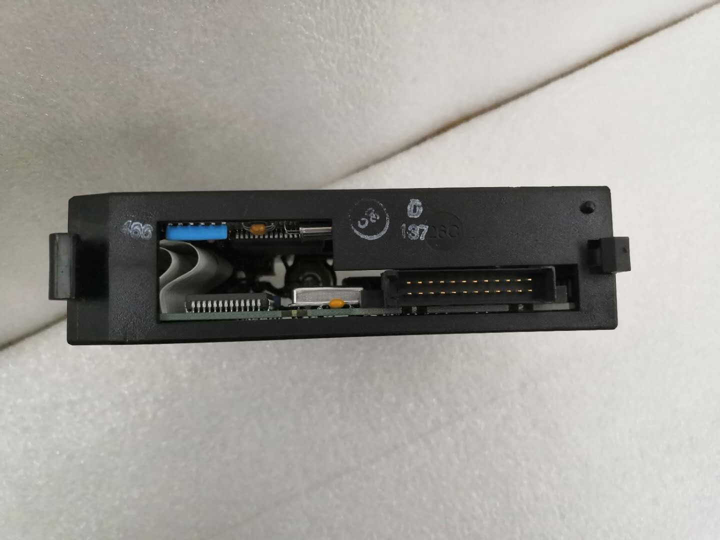
The module’s primary interface capability is two independent programmable serial ports accessed through a common 25-pin D-sub connector on the front panel. The IC693CBL305 Y-cable (included with the module) splits the single connector into two separate ports:
- Port 1 (RS-485/RS-422) : Electrically isolated half-duplex/full-duplex serial port supporting Modbus RTU Master/Slave, ASCII, GE Fanuc CCM, and SNP protocols. The electrical isolation provides superior noise immunity for multi-drop networks in industrial environments. Configurable baud rates from 300 bps to 115.2 kbps.
- Port 2 (RS-232 or RS-485) : Configurable port supporting RS-232 point-to-point communication (for HMI, programmers, barcode readers, scales, printers) or RS-485 multi-drop operation (similar protocol support to Port 1). The PCM301 offers RS-485 capability on Port 2, which is a key difference from the PCM300 (Port 2 RS-485 only).
Both ports can operate independently with different protocols, enabling mixed-protocol applications—simultaneous Modbus RTU Master operation on Port 1 while communicating with an HMI via DF1 protocol on Port 2.
Independent Execution and CPU Offloading
Unlike standard communication modules that rely on main CPU scan cycle for data exchange, the PCM301 executes user programs independently through its own microprocessor and RAM. This independence allows the coprocessor to perform complex communication tasks, data preprocessing, protocol conversion, and closed-loop control functions without consuming main CPU scan time. The PCM301 can execute MegaBasic or C programs that process serial communication at high speeds, filter and format data, then exchange results with the main CPU via backplane shared memory areas (%R registers). This offloading capability is critical for applications where communication load would otherwise extend main CPU scan cycles and degrade control response.
Configuration Modes and Programming Options
The PCM301 supports three primary configuration modes:
- CCM Mode: One or two independent CCM (Communications Co-Processor Module) ports for high-speed GE Fanuc SNP protocol communication between GE PLCs or GE HMI devices
- Mixed Mode: One CCM port combined with a MegaBasic application using one serial port for custom protocol handling
- MegaBasic Mode: MegaBasic application using one or both serial ports for complete custom protocol development and data processing
Programming languages supported include MegaBasic (enhanced BASIC dialect optimized for GE 90-30 environment), standard BASIC, and C language. The PCM301 is programmed via PCOP (PCM Development Software) or TERMF (terminal emulator software) running on a host computer connected to the PCM’s RS-232 programming port (via IC690CBL701/702/705 cables). Once programmed, the module operates independently without requiring the programming computer to remain connected.
Memory Expansion and Battery Backup
The 192KB RAM on the PCM301 is backed up by a lithium battery (IC693ACC301, package of 2) mounted inside the faceplate. The battery is disconnected during factory shipment and must be connected prior to module installation to retain programs in RAM during power loss. For long-term storage, the battery should be disconnected to prevent depletion. The supports expansion memory boards (IC697MEM713/715/717/719) for applications requiring additional memory beyond the base 192KB—critical for complex MegaBasic programs or large data buffering applications.
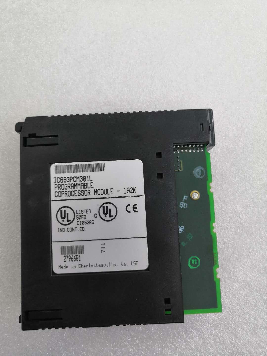
GE IC693PCM301
Core Technical Specifications
- Microprocessor: 8MHz 80C188
- Total Memory: 192KB RAM
- User MegaBasic Memory: 47KB (nominal user-available memory for MegaBasic programs)
- Expansion Memory Support: IC697MEM713 (64KB), IC697MEM715 (128KB), IC697MEM717 (256KB), IC697MEM719 (512KB)
- Memory Backup: Lithium battery (IC693ACC301, package of 2)
- Programming Languages: MegaBasic, Standard BASIC, C
- Protocols Supported: Modbus RTU Master/Slave, GE Fanuc CCM/SNP, ASCII (custom), DF1
- Port 1: RS-485/RS-422 (electrically isolated), half-duplex/full-duplex, configurable 300 bps-115.2 kbps
- Port 2: RS-232 (point-to-point) or RS-485 (multi-drop), configurable 300 bps-115.2 kbps
- Front Connector: 25-pin D-sub common connector (both ports accessed via this connector)
- Cable Included: IC693CBL305 Wye cable (splits single connector into two separate ports)
- Programming Cables: IC690CBL701 (IBM XT compatible 9-pin), IC690CBL702 (IBM AT compatible 9-pin), IC690CBL705 (IBM PS/2 compatible 25-pin)
- LED Indicators: OK (module status—normally ON), US1 (Port 1 activity—customizable), US2 (Port 2 activity—customizable)
- Restart Button: Switches module between RUN and PROGRAM modes
- Backplane Current Draw: 425mA @ 5VDC (typical)
- Power Source: Backplane +5VDC (no external power required)
- Mounting Location: CPU baseplate only—any slot except slot 1 (CPU module slot)
- Compatibility: Modular CPUs only (CPU331/341/350/351/352/360/363/364); NOT compatible with Embedded CPUs (311/313/323); NOT compatible with Expansion or Remote racks
- Operating Temperature: 0°C to 60°C
- Storage Temperature: -40°C to 85°C
- Configuration Software: PCOP (PCM Development Software) IC641SWP061, TERMF terminal software IC641SWP063, Logicmaster 90 programming software
- Documentation: GFK-0255 (Series 90 Programmable Co-Processor Module and Support Software User’s Manual), GFK-0256 (MegaBasic Language Reference), GFK-0487 (PCOP User’s Manual), GFK-0771 (C Programmer’s Toolkit)
Customer Value & Operational Benefits
Independent Processing Offloads Main CPU Scan Cycle
The ‘s independent microprocessor and memory enable execution of communication-intensive tasks without consuming main CPU scan time. In applications polling 20+ Modbus RTU slave devices, executing custom protocol drivers, or performing real-time data preprocessing, the main CPU scan cycle would be significantly extended if these tasks were executed within the ladder logic scan. The executes these tasks asynchronously—communication occurs at the programmed rate regardless of main CPU scan time, and processed data is exchanged via backplane memory without main CPU involvement. Field measurements show typical main CPU scan cycle reduction of 30-50% when communication tasks are offloaded to , resulting in faster control loop execution and improved responsiveness for time-critical applications such as motion control or closed-loop process regulation.
Dual Port Multi-Protocol Capability Enables Unified Communication Architecture
The ‘s dual independent ports support simultaneous operation of different protocols, eliminating the need for multiple communication modules or external protocol converters. A single can poll multiple Modbus devices via Port 1 (RS-485) while simultaneously exchanging data with an Allen-Bradley DF1 HMI via Port 2 (RS-232). This mixed-protocol capability reduces hardware count, simplifies cabinet wiring, and eliminates external gateway devices that introduce additional failure points. The electrical isolation on Port 1 provides robust noise immunity for RS-485 multi-drop networks in environments with VFDs, motor starters, or welding equipment, while Port 2’s RS-232 point-to-point mode supports reliable connection to programming terminals or printers without requiring isolation.
Custom Programming Flexibility for Non-Standard Device Integration
Support for MegaBasic and C programming enables development of custom communication drivers for non-standard serial devices that lack standard protocol support. Barcode scanners, weighing scales with proprietary ASCII formats, specialized sensors with custom data formats, and legacy equipment with outdated protocols can be integrated into the PLC system without requiring external protocol converters or hardware modifications. Engineers can develop MegaBasic programs that parse custom ASCII strings, filter valid data, perform scaling calculations, and write formatted results directly to main CPU %I memory. This capability is particularly valuable in OEM equipment where proprietary sensor interfaces must be preserved while enabling integration into modern PLC architectures.
Memory Expansion Supports Large-Scale Data Buffering and Protocol Development
The ‘s support for expansion memory boards (up to 512KB additional memory) enables large-scale data buffering applications and complex protocol development. In SCADA RTU applications, the can buffer historical data, perform local data logging, and execute alarm processing independently of the main CPU or SCADA master polling rate. For complex protocol conversion applications (e.g., Modbus to DF1 gateway), expansion memory provides space for protocol stacks, data conversion tables, and buffering for both protocols. The memory expansion capability transforms the from a simple coprocessor into a standalone intelligent node capable of autonomous operation even during main CPU downtime or SCADA communication failures.
GE IC693PCM301
Field Engineer’s Notes (From the Trenches)
The compatibility restrictions are absolute— will not function in embedded CPU racks (311/313/323) or in expansion/remote racks. I’ve wasted hours troubleshooting a that appeared dead, only to discover it was installed in an expansion rack. The module requires direct connection to a modular CPU via the CPU baseplate backplane for proper operation. Always verify the CPU model before specifying a PCM—embedded CPUs do not support PCM communication via backplane architecture. For facilities with mixed 90-30 installations (both modular and embedded CPUs), establish clear labeling on CPU baseplates to prevent accidental PCM installation in incompatible racks.
Battery connection during installation is frequently overlooked. The lithium battery ships disconnected from its clip to prevent depletion during storage. If you install the module without connecting the battery, your programs in RAM will be lost on the first power cycle. I’ve encountered sites where technicians replaced a PCM and assumed programs would persist from the previous module, only to discover the battery was never connected and the new module lost the application during the first power cycle after maintenance. Always connect the battery prior to powering up the rack for the first time after PCM installation. Use IC693ACC301 replacement batteries (package of 2) and replace both batteries when either battery fails—mismatched battery capacities can cause uneven discharge and premature warnings.
The IC693CBL305 Y-cable is included with each , but I’ve seen sites accumulate various Y-cables over time and mix them between PCM models. The PCM300 uses IC693CBL304, while and PCM311 use IC693CBL305. Using the wrong Y-cable won’t damage the module, but pin assignments differ and you’ll get no communication or intermittent connections. Always verify the cable model matches the PCM catalog number. If you’ve lost track of which cable is which, label them at the connector with the PCM model they serve—this confusion causes significant downtime during maintenance when multiple PCMs are in the facility.
Port 2’s RS-485 capability on the is a key differentiator from the PCM300 (Port 2 RS-485 only). However, enabling RS-485 on Port 2 requires jumper configuration within the module—refer to GFK-0255 for jumper settings. I’ve configured PCMs with RS-232 on Port 2 when the application actually required RS-485 multi-drop, causing communication failures when connecting multiple devices. Verify your application’s requirements before configuration: RS-232 for point-to-point single device (HMI, programmer), RS-485 for multi-drop networks. Remember that Port 1 is always RS-485/RS-422 with electrical isolation, while Port 2 is configurable between RS-232 and RS-485.
The restart button’s function is frequently misunderstood. Pressing the restart button does NOT power cycle the module—it switches between RUN and PROGRAM modes. To properly reset the PCM after downloading a new program, press the restart button to switch to PROGRAM mode, download the program, then press restart again to return to RUN mode. I’ve encountered technicians continuously pressing restart during runtime trying to “reset” the module, which causes intermittent communication drops as the module toggles between modes. Only use the restart button during program download or mode changes—never press it during normal operation. For complete module reset (power cycle), remove and reinstall the module or cycle power to the entire rack.
Programming the requires patience—MegaBasic development via PCOP software involves compiling programs on a host computer then downloading to the PCM via serial connection. The download speed is limited to the baud rate configured for the programming port (typically 19.2 kbps or 38.4 kbps for reliability). Large programs with expansion memory can take 10-20 minutes to download. Avoid aborting downloads mid-process—corrupted programs can cause the PCM to enter an undefined state requiring battery disconnection to clear RAM. Use the highest reliable baud rate your cabling and noise environment support (typically 38.4 kbps for industrial environments), and ensure the programming computer remains connected and powered throughout the entire download process.
Real-World Applications
Automotive Assembly Line Multi-Protocol Data Gateway
An automotive assembly facility implemented modules as communication gateways between the GE 90-30 control system and multi-vendor field devices. Port 1 (RS-485) operated as Modbus RTU Master polling 32 VFDs, 16 temperature controllers, and 8 power meters across the assembly line. Port 2 (RS-232) communicated with an Allen-Bradley PanelView HMI via DF1 protocol displaying real-time production data and operator setpoints. The ‘s independent execution polled Modbus devices at 1.92 kbps regardless of main CPU scan cycle, filtered and formatted data, and exchanged results with the main CPU via %R memory. This architecture reduced main CPU scan cycle from 45ms to 28ms, improving motion control response and eliminating scan cycle overruns that previously caused occasional motion faults during high-speed assembly operations.
Water Treatment Plant SCADA RTU with Local Logic
A municipal water treatment plant deployed modules as remote terminal units (RTUs) at unmanned pump stations. Each connected to the central SCADA system via Port 1 (RS-485) operating as Modbus RTU Slave, while simultaneously executing local pump control logic via MegaBasic program. The local logic executed pump sequencing, pressure regulation, and fault detection independently of SCADA communication, ensuring continued operation during SCADA communication failures. The ‘s battery backup preserved local logic and historical data during power outages, while expansion memory (IC697MEM715, 128KB) provided data buffering for up to 24 hours of historical SCADA data transmission. This architecture reduced SCADA communication bandwidth requirements and improved local response time by eliminating round-trip communication for routine control decisions.
Food Processing Packaging Line Custom Device Integration
A food processing facility’s packaging line incorporated barcode scanners, weighing scales, and label printers with proprietary ASCII protocols. modules with custom MegaBasic programs parsed these proprietary ASCII strings, validated data integrity, performed scaling calculations (converting raw weight values to engineering units), and formatted results for main CPU consumption. The ‘s dual ports enabled simultaneous operation: Port 1 (RS-485) polling standard Modbus devices on the line, while Port 2 (RS-232) communicated with the proprietary devices via custom ASCII protocol. This unified communication architecture eliminated external protocol converters and reduced hardware count by 40%. The custom programming capability enabled integration of legacy barcode scanners that lacked standard protocol support, preserving equipment investment while modernizing the control system.
Material Handling Conveyor System Data Preprocessing
A distribution center’s conveyor system used modules for high-speed barcode scanning and data preprocessing. Barcode scanners on conveyor lines transmitted ASCII strings to Port 2 (RS-232) at 115.2 kbps. The ‘s MegaBasic program filtered invalid barcodes, performed database lookups to verify shipping routes, calculated destination zones, and wrote formatted results to main CPU %I memory. The main CPU received preprocessed destination zone data directly, eliminating string parsing and database lookup logic from the main scan cycle. This preprocessing reduced main CPU scan cycle by 35% and improved conveyor throughput by 12% due to faster routing decisions. The ‘s independent execution handled barcode data processing asynchronously—high scanner peak rates during surge periods did not extend the main CPU scan cycle.
High-Frequency Troubleshooting FAQ
Q: Can IC693PCM301 be installed in expansion or remote racks?
A: No, the must be installed in the CPU baseplate only (any slot except slot 1/CPU module slot). It will not function in expansion racks, remote racks, or embedded CPU (311/313/323) racks. The module requires direct backplane connection to a modular CPU for proper communication and power distribution. If you need coprocessor functionality in remote locations, consider using remote I/O racks with modular CPUs installed in each remote rack, or explore alternative communication architectures that do not require PCM in remote racks.
A: The primary differences are memory capacity and Port 2 configuration:
- IC693PCM300: 160KB total RAM, 35KB user MegaBasic memory, Port 1 RS-485 only, Port 2 RS-485 only (no RS-232 option on Port 2)
- IC693PCM301: 192KB total RAM, 47KB user MegaBasic memory, Port 1 RS-485/RS-422 with isolation, Port 2 RS-232 OR RS-485 configurable
- IC693PCM311: 640KB total RAM, 190KB user MegaBasic memory, Port 1 RS-485/RS-422 with isolation, Port 2 RS-232 OR RS-485 configurable
The PCM311 offers significantly larger memory capacity for complex applications, while the provides the best balance of memory and flexible port configuration (RS-232 on Port 2) for most mixed-protocol applications.
A: Programming cables IC690CBL701/702/705 connect the ‘s RS-232 programming port to various computer serial ports. IC690CBL701 is for IBM XT compatible 9-pin serial ports, IC690CBL702 is for IBM AT compatible 9-pin serial ports, and IC690CBL705 is for IBM PS/2 compatible 25-pin serial ports. These cables are NOT included with the —you must order them separately. Modern computers without native serial ports require USB-to-serial adapters; ensure the adapter provides true RS-232 signaling (not just voltage levels) for reliable PCM programming. Connect the cable, configure PCOP or TERMF software for the correct COM port, and establish communication before attempting program downloads.
A: If the lithium battery fails or is disconnected during operation, the will lose all programs stored in RAM on the next power cycle. However, the module will continue operating normally until power is removed—the battery only maintains RAM content during power loss. The OK LED will remain ON during operation even with a failed battery, so battery failure is not immediately indicated. Monitor the battery voltage during periodic maintenance (typically 3V+ when healthy, below 2.7V indicates imminent failure). Replace batteries using IC693ACC301 (package of 2) and replace both batteries simultaneously—mismatched battery capacities can cause uneven discharge. For critical applications where program loss is unacceptable, consider using expansion memory boards with EPROM options (if available) for permanent program storage.
A: No, programs cannot directly access main CPU %I or %Q I/O modules. Data exchange between and main CPU occurs via backplane shared memory areas (%R registers). The writes data to %R memory that the main CPU reads, and the main CPU writes data to %R memory that the reads. This indirect exchange requires careful memory mapping in both the PCM program and the main CPU ladder logic. Configure COMMREQ blocks in the main CPU to exchange data with the PCM, and define memory ranges in the PCM program that correspond to the main CPU %R addresses. Never attempt to access %I or %Q directly from PCM programs—this will cause addressing errors and undefined behavior.
Q: How do I configure Port 2 for RS-232 vs. RS-485 operation?
A: Port 2 configuration between RS-232 and RS-485 requires jumper settings within the module. Refer to GFK-0255 (Series 90 Programmable Co-Processor Module User’s Manual) for the specific jumper configuration table. The jumpers are typically labeled on the circuit board and must be set before module installation or during maintenance with power removed. Incorrect jumper settings will cause communication failures—if Port 2 is configured for RS-232 but you attempt RS-485 multi-drop communication, only one device (the first connected) will communicate, and additional devices will not respond. Always verify jumper settings match your application requirements before powering up the rack after PCM installation or jumper changes.
Commercial Availability & Pricing
Please note: The listed price is not the actual final price. It is for reference only and is subject to appropriate negotiation based on current market conditions, quantity, and availability.


