
Description
System Architecture & Operational Principle
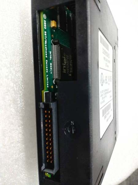
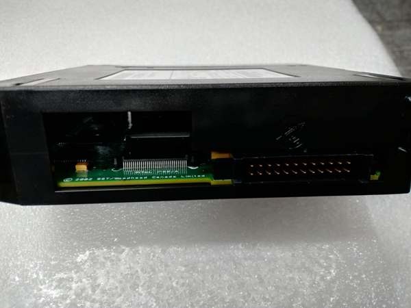
The IC693PBM200 occupies a single slot on the GE 90-30 backplane (any slot except slot 1 of modular CPU baseplates) and functions as a PROFIBUS DP Master at Level 1-2 of the Purdue Model (Basic Control/Supervisory Control). It interfaces with the CPU via %I and %Q memory mapping—sending output commands from %Q to PROFIBUS slaves and receiving input data from slaves into %I. The module manages the PROFIBUS DP protocol stack independently from the CPU, performing cyclic data exchange, slave diagnostics, and bus management.
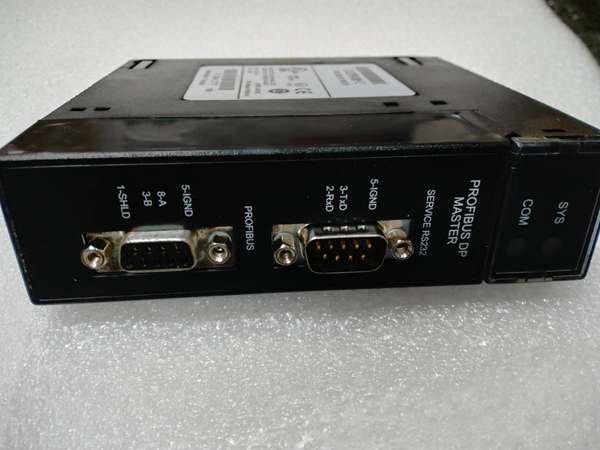
The IC693PBM200 uses a 9-pin female D-sub connector for the PROFIBUS RS-485 network interface, supporting daisy-chain (linear) topologies with terminating resistors at both ends of the bus. An RS-232 service port (9-pin male D-sub) provides access for firmware upgrades using programming software. Two LED indicators (SYS and COM) display module status—SYS indicates module health, COM indicates network communication activity.
Upstream, the CPU writes to %Q addresses mapped to slave outputs during each PLC scan; downstream, the module transmits these outputs over the PROFIBUS DP network at the configured baud rate. The module supports SYNC/FREEZE modes for coordinated multi-slave control—SYNC forces all slaves to simultaneously accept new output data, while FREEZE freezes slave outputs for synchronized operations. This is critical for applications requiring precise timing coordination across multiple distributed devices.
Clear Mode vs. RUN Mode
A critical architectural distinction from the legacy HE693PBM101: the IC693PBM200 enters Clear Mode whenever the PLC is not scanning I/O (STOP mode, power-up before PLC starts, or PLC fault). In Clear Mode, the module deasserts all outputs to slaves and clears the bus, ensuring a defined off state during PLC initialization. This prevents uncontrolled output activation during PLC startup—a safety feature not present in earlier modules. Once the PLC begins scanning I/O, the module transitions to RUN mode and begins cyclic data exchange.
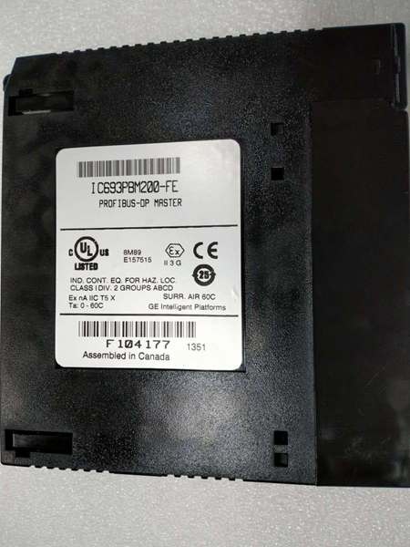
IC693PBM200
Core Technical Specifications
- Physical Interface: Single-slot width, 9-pin female D-sub PROFIBUS port, 9-pin male RS-232 service port
- PROFIBUS Protocol: DP Master only (DP-V0 compliant), does not support PA directly (requires DP/PA coupler for PA devices)
- Network Topology: Daisy-chain (linear) RS-485 bus with terminating resistors at both ends
- Supported Slaves: Maximum 125 PROFIBUS DP slave devices
- Data Exchange per Slave: 244 bytes input + 244 bytes output (488 bytes total per slave)
- CPU-Module Data Limit: 3,972 bytes input data (module to CPU), 3,972 bytes output data (CPU to module)
- Baud Rates: All standard rates—9.6K, 19.2K, 93.75K, 187.5K, 500K, 1.5M, 3M, 6M, 12M bps
- Special Functions: SYNC/FREEZE modes, Slave Status Bit Array, Network diagnostic counters, DP master diagnostic counters
- Status Information: Slave Diagnostic Address table, firmware module revision, slave status area (128 bits default, twice HE693PBM101)
- Configuration Software: Proficy Machine Edition Logic Developer version 2.6 or later (some sources indicate 3.0+ for certain features)
- CPU Requirement: Firmware version 8.00 or later (CPU311/313/323, 331, 341, 350, 352, 360, 363, 364 supported; CPU release 10.60+ recommended for large-scale applications)
- Backplane Current Draw: 450mA @ 5V DC (typical)
- Environmental: Operating temperature 0°C to 60°C, storage -40°C to 85°C
- Status LEDs: SYS (System) and COM (Communication) indicators, PROFIBUS-compliant
- Firmware Upgrade: Via RS-232 service port
- Mounting: Any I/O slot in CPU, expansion, or remote baseplate—except slot 1 of modular CPU baseplates (reserved for power supply)
- Slave Status Bit Organization: Arranged by bus address (not by order of appearance in configuration—critical difference from HE693PBM101)
Customer Value & Operational Benefits
Standard PROFIBUS Integration Enables Cross-Platform Interoperability
The IC693PBM200 provides GE 90-30 PLCs with industry-standard PROFIBUS DP Master functionality, enabling seamless integration with Siemens ET200 remote I/O, Siemens S7 PLCs (as slaves), ABB drives, Schneider devices, and hundreds of other PROFIBUS-compliant products. This interoperability eliminates the need for proprietary GE networks (like Genius) in mixed-brand facilities. In brownfield projects where plant standards mandate PROFIBUS as the fieldbus protocol, GE controllers can participate without gateways or protocol converters. This reduces hardware costs—gateway devices typically cost $2,000-5,000—and simplifies network architecture by maintaining a single fieldbus standard across the facility.
High Slave Capacity Supports Large-Scale Distributed I/O
With support for up to 125 PROFIBUS DP slaves and 244 bytes input/output per slave, the IC693PBM200 can manage extensive distributed I/O architectures. A single 90-30 PLC with an IC693PBM200 can control multiple remote I/O racks (each using a distributed I/O gateway as a slave), variable frequency drives, motor starters with intelligence, and operator panels across a facility. The 3,972-byte CPU-module data limit accommodates complex distributed I/O configurations—up to approximately 16 slaves at maximum capacity (16 × 244 = 3,904 bytes) or more slaves at reduced per-slave data allocations. This scalability supports applications from small machine control (5-10 slaves) to large process plants (80+ slaves) without requiring multiple master modules.
SYNC/FREEZE Modes Enable Coordinated Multi-Axis Control
The SYNC/FREEZE modes provide deterministic coordination across multiple slave devices—critical for applications requiring precise synchronized motion or state changes. SYNC forces all slaves to accept new output data simultaneously, ensuring that all actuators begin motion at exactly the same instant. FREEZE freezes slave outputs in their current state while the PLC performs calculations, then releases them simultaneously. This functionality is essential for coordinated multi-axis servo systems, flying shear applications, and web handling processes where multiple axes must start/终止 in precise synchronization. Without SYNC/FREEZE, variations in data transmission times across the bus would cause timing jitter and miscoordination.
IC693PBM200
Field Engineer’s Notes (From the Trenches)
The slave status bit arrangement difference from HE693PBM101 is a migration trap that causes hours of debugging. The legacy HE693PBM101 arranges slave status bits in the order slaves appear in the configuration file—the first slave in your configuration gets bit 0, the second gets bit 1, and so on. The arranges slave status bits by PROFIBUS bus address—slave at address 3 maps to bit 3, regardless of where it appears in your configuration. When migrating from HE693PBM101 to , if your program logic assumes the legacy bit arrangement, you’ll get completely wrong slave status indications. I’ve seen technicians chase ghost slave faults for days before realizing the bit mapping had changed. Document your existing slave addresses before migration and restructure your slave status logic to use address-based bit mapping.
Another gotcha: the 3,972-byte CPU-module data limit includes both input and output data, plus the slave status bit array. This is a hard limit—you cannot exceed it regardless of the 244-byte-per-slave limit. If you configure 20 slaves each with 200 bytes input and 200 bytes output (20 × 400 = 8,000 bytes), the configuration software won’t 终止 you, but the module will fault at runtime. The symptom? The COM LED flashes or the SYS LED indicates a fault, but individual slaves appear healthy. Divide your intended total byte count by 3,972—if the result exceeds 1, reduce per-slave data or use fewer slaves. For high-density applications, consider using remote I/O gateways that aggregate multiple field devices into a single slave address, reducing the number of PROFIBUS slaves the master must manage.
Clear Mode is a feature and a potential nuisance. When the PLC 终止s (program mode, fault condition, or power-up), the enters Clear Mode—deasserting all outputs and clearing the bus. This is excellent for safety—ensuring drives don’t spin up unexpectedly. But during commissioning, when you’re cycling PLC power frequently, the Clear Mode resets all slaves to their default states. Drives configured for auto-restart may not restart; smart I/O may lose configured parameters. The workaround? For commissioning, use the PLC’s RUN/STOP switch rather than cycling power when possible, and verify slave auto-restart settings before initial power-up. Document which slaves lose configuration in Clear Mode and prepare to re-configure them during commissioning.
Baud rate selection is critical for long bus lengths. The supports up to 12 Mbps, but at that rate, the maximum bus length drops to just 100 meters (with proper cabling). At 1.5 Mbps, you can run 400 meters; at 9.6 Kbps, you can achieve 1,200 meters. In facilities where the PLC cabinet is far from distributed field devices, calculate the total bus length (sum of all cable segments, not just the longest run) and select the highest baud rate that meets the length requirement. I’ve seen technicians configure 12 Mbps for a 500-meter bus—then wonder why slaves randomly disconnect due to signal degradation. Use the PROFIBUS length/baud rate table: 9.6K/1,200m, 19.2K/1,200m, 93.75K/1,200m, 187.5K/1,000m, 500K/400m, 1.5M/200m, 3M/100m, 6M/100m, 12M/100m (reduced at high frequencies).
Real-World Applications
Automotive Assembly Line Distributed Control
In automotive final assembly plants, the enables a GE 90-30 PLC to coordinate multiple assembly stations via PROFIBUS DP. Slaves include Siemens ET200 remote I/O racks (containing sensors for part presence, fastening torque verification), Allen-Bradley PowerFlex drives (for conveyor speed control), and operator panels at each station (for manual mode selection and fault acknowledgment). The SYNC mode ensures that all conveyor drives start simultaneously during line acceleration, preventing part jams due to miscoordinated motion. The 244-byte-per-slave capacity accommodates complex I/O structures at each station—discrete inputs, analog torque feedback, and status data. The Clear Mode feature ensures all drives 终止 if the PLC faults or loses power, providing a critical safety measure in high-speed assembly environments.
Water Treatment Plant Remote I/O Network
In municipal water treatment facilities, the connects a central GE 90-30 PLC to distributed I/O nodes across multiple process areas (intake, filtration, disinfection, distribution). Each area uses a distributed I/O gateway (configured as a PROFIBUS DP slave) to interface with local sensors (flow meters, pressure transmitters, chlorine analyzers) and actuators (pump starter coils, valve actuators). The 125-slave capacity supports extensive geographic distribution of I/O, while the 244-byte per-slave limit accommodates the dense sensor arrays typical in water treatment processes. The RS-485 bus topology reduces wiring costs—instead of running individual sensor wires back to the central PLC cabinet, shielded PROFIBUS cable daisy-chains between process areas, using a single cable for up to 126 devices (125 slaves + master). This reduction in field wiring can save $50,000-100,000 in cabling and installation costs for large treatment plants.
Packaging Machine Multi-Axis Synchronization
In high-speed packaging machinery, the coordinates multiple servo axes and pneumatic actuators using the SYNC/FREEZE modes for precise synchronization. Slaves include Siemens S120 servo drives (for film tension, sealing, and cutting axes), pneumatic valve manifolds with integrated PROFIBUS interfaces, and rotary encoders for position feedback. The SYNC command ensures all axes accelerate simultaneously during product changes, while FREEZE holds current positions during PLC calculations for recipe changes. The 12 Mbps baud rate provides sub-millisecond data exchange, enabling the high-speed coordination required for packaging rates exceeding 200 packages per minute. The RS-232 service port allows firmware upgrades during machine downtime without removing the module from the cabinet—critical for maintaining production schedules.
High-Frequency Troubleshooting FAQ
A: No, the is a PROFIBUS DP Master only—it cannot function as a slave. If you need a GE 90-30 PLC to function as a PROFIBUS slave (controlled by another master), you must use the HE693PBS201 (PROFIBUS DP Slave Module) or IC693PBS200 (90-30 Slave module). The is designed to control slaves, not be controlled. Attempting to configure it as a slave will not work—the module is hardwired for master functionality only.
A: The is the 90-30 native version, while the is the Series 90 Master version. Key differences: (1) Slave status area size— has 128 bits default vs. 64 bits on ; (2) Slave status bit arrangement— arranges by bus address, by configuration order; (3) Clear Mode— enters Clear Mode when PLC not scanning, does not; (4) Configuration software— requires Proficy Machine Edition 2.6+, uses older software; (5) Mounting restrictions— cannot be installed in slot 1 of modular CPU baseplates, has no slot restriction. Migrating from requires adjusting slave status logic and Clear Mode handling in your program.
Q: How do I configure SYNC/FREEZE modes?
A: SYNC and FREEZE modes are configured in the Proficy Machine Edition hardware configuration for the . In the slave configuration properties, you can assign SYNC/FREEZE groups. A SYNC group is a collection of slaves that will receive new output data simultaneously when the PLC issues a SYNC command. A FREEZE group freezes slave outputs while the PLC performs calculations, then releases them together. To use these modes, the slaves must support SYNC/FREEZE (most PROFIBUS DP-V0 compliant slaves do). In your PLC program, use the COMMREQ function block to issue SYNC or FREEZE commands to the . The exact COMMREQ command codes are documented in the GFK-2121 user manual—typically command 2002 for SYNC and 2003 for FREEZE, with the group number as a parameter.
Q: Why does the COM LED flash intermittently?
A: A flashing COM LED indicates network communication activity—this is normal behavior during cyclic data exchange. The COM LED should blink continuously when the module is in RUN mode and communicating with slaves. However, if the COM LED flashes irregularly (rapid bursts followed by long pauses), it may indicate: (1) Bus contention or collisions on an improperly configured network; (2) Slaves going offline and coming back online; (3) Baud rate mismatch or signal degradation causing retransmissions. Use the network diagnostic counters available from the to check for error frames, bus off conditions, or retransmission counts. High error counts indicate physical layer problems—check cable termination, verify all slaves are configured for the same baud rate, and inspect for ground loops.
A: The is a PROFIBUS DP Master only—it does not directly support PROFIBUS PA (Process Automation) devices. PROFIBUS PA uses a different physical layer (IEC 61158-2) and voltage levels optimized for intrinsic safety in hazardous areas, while DP uses standard RS-485. To control PA devices with an , you must use a DP/PA coupler (such as Siemens DP/PA Link or Pepperl+Fuchs coupler) that converts between DP and PA networks. The coupler appears as a DP slave to the and functions as a PA master to the PA field devices. This two-tier architecture allows DP masters to control PA devices without requiring PA master functionality in the PLC.
Commercial Availability & Pricing
Please note: The listed price is not the actual final price. It is for reference only and is subject to appropriate negotiation based on current market conditions, quantity, and availability.


