
Description
System Architecture & Operational Principle
The IC693MDR390 occupies a single slot on the GE 90-30 universal backplane, functioning as a discrete sourcing output interface at Level 1 of the Purdue Model (Basic Control). It receives output commands from the CPU via %Q memory mapping and switches 12-24V DC power to field devices. Upstream, the CPU writes output states during each PLC scan; downstream, the module provides current limiting, group fusing, and inductive flyback protection for field device control.
The module’s sourcing (source) configuration means it sources current from the module output terminal to the field device load, with the load return connected to DC common (0V). This matches the input configuration of most modern field devices—NPN inputs on relays, indicator LEDs, and some solenoid valve coils. Each group of 4 outputs shares a common fuse (2A total per group), providing overcurrent protection while allowing individual point current limits of 0.5A. The module includes built-in flyback diodes for inductive loads, preventing voltage spikes from de-energizing coils from damaging the output transistors.
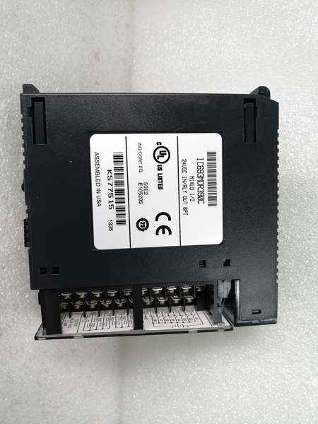
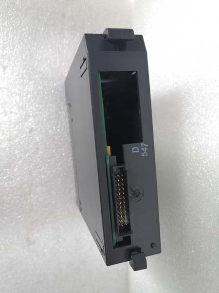
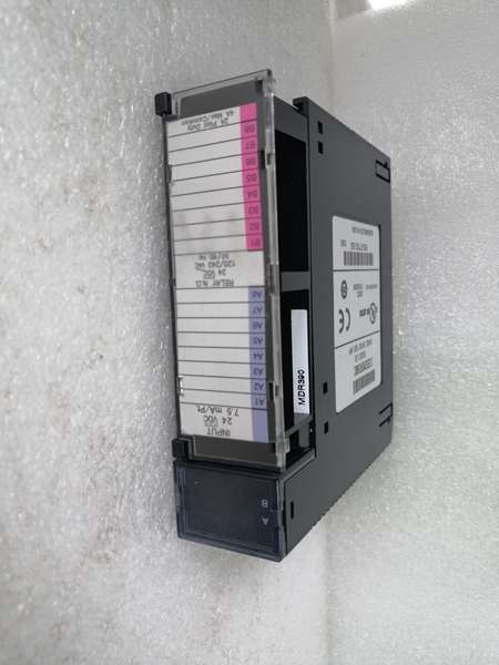
GE IC693MDR390
Core Technical Specifications
- Physical Interface: 40-pin terminal block (2 connectors, 16 points each) or front-facing removable terminal block option
- Output Type: 32-point discrete output, 12-24V DC, sourcing (source configuration)
- Output Voltage Range: 12-24V DC (nominal 24V DC)
- Output Current: 0.5A per point maximum, 2A per 4-point group maximum
- Isolation: 1500V RMS optical isolation between field side and backplane; outputs share common DC return
- Backplane Current Draw: Approximately 650mA @ 5V DC
- Response Time: 1ms typical turn-on, 1ms typical turn-off (inductive loads may have longer decay)
- LED Indicators: Individual LEDs per output point (ON when output energized) plus module status LEDs
- Environmental: Operating temperature 0°C to 60°C (32°F to 140°F), humidity 5-95% non-condensing
- Terminal Block: 40-pin plug-in terminal block, supports wire gauges 22-14 AWG
- Field Wiring: Sourcing configuration—module outputs source +24V to field device, load return to DC common (0V)
- Protection: Individual point current limiting, group fusing (4 outputs per 2A fuse), built-in flyback diodes for inductive loads
- Diagnostic Capabilities: No onboard diagnostics beyond LED indication (discrete module, not intelligent)
- Short-Circuit Protection: Individual point current limiting plus group fuse protection
Customer Value & Operational Benefits
High-Density Output Capability Reduces Module Count
With 32 output points in a single slot, the IC693MDR390 significantly reduces the number of output modules required for applications with high discrete point counts. Each 32-point module replaces two 16-point modules or four 8-point modules, freeing backplane slots for other module types or reducing the physical rack size. In space-constrained installations (marine control panels, skid-mounted equipment, retrofit projects), this density is critical—it allows more output capacity per cabinet footprint without sacrificing individual point indication or protection.
Group Fusing Protection Prevents Catastrophic Failure
The IC693MDR390’s 4-point group fusing (2A per group) provides targeted overcurrent protection that prevents a single short-circuit from disabling all 32 outputs. If one output shorts to ground, only its 4-point group is affected—other groups continue operating normally. This design improves fault tolerance compared to modules with a single common fuse for all outputs, where one short would disable the entire module. For critical applications where output availability is paramount (e.g., safety interlocks, emergency shutdown systems), this group-level protection minimizes the impact of field wiring faults.
Built-In Flyback Protection for Inductive Loads
The module includes built-in flyback diodes for inductive load protection, eliminating the need for external clamp diodes across relay coils, solenoid valves, or motor starter coils. When an inductive load de-energizes, the collapsing magnetic field generates a high-voltage spike that can damage output transistors. The built-in diodes clamp these spikes to safe levels, protecting the module and reducing external component count. This simplifies wiring and reduces the risk of field technicians omitting external protection components—a common cause of output module failure in retrofits.
GE IC693MDR390
Field Engineer’s Notes (From the Trenches)
Here’s a gotcha that’s destroyed multiple IC693MDR390 modules: the 2A per 4-point group fuse rating is not a suggestion—it’s a hard limit. I’ve seen techs daisy-chain two solenoid valves (each drawing 0.8A) on outputs 1 and 2 of the same group, thinking they’re under the 0.5A per-point limit. But 0.8A + 0.8A = 1.6A continuous, which is fine, but when both valves energize simultaneously during startup, the inrush current exceeds 2A and blows the group fuse. The lesson? Calculate worst-case simultaneous current per group, not per-point. If you have multiple high-current loads on the same group, distribute them across groups or add external relays to reduce module output current draw. Also, verify your load return wiring—the module sources +24V to the field device, so the load return must go to DC common (0V), not to the module output terminal. I’ve seen techs wire the load return to another output terminal, creating sneak paths that blow fuses or damage outputs. Finally, the backplane current draw is approximately 650mA at 5V DC—significantly higher than many input modules. If you’re loading a rack with multiple 390 modules and analog modules, calculate your total backplane current. I’ve encountered cabinets where adding just one 390 pushed the 5V supply from 80% to 95% load, causing intermittent CPU faults during output storms.
Real-World Applications
Automotive Assembly Line Solenoid Valve Control
In automotive final assembly plants, the IC693MDR390 controls 32 solenoid valves on pneumatic actuators for divert gates, clamp cylinders, and lift mechanisms. The module’s 0.5A per-point capacity handles most standard pneumatic valves, while the 2A per-group fusing protects against short-circuits in valve wiring harnesses. The built-in flyback diodes eliminate the need for external clamp diodes across each valve coil, simplifying wiring in the crowded control cabinet. The per-point LED indicators enable rapid troubleshooting—technicians can visually identify which valve output is energized or which group fuse has blown without connecting to the PLC. Output states map to sequencing logic—the PLC energizes valves in the correct sequence to divert workpieces, clamp parts, and lift assemblies.
Packaging Machine Indicator Light and Relay Control
In high-speed packaging machinery, the IC693MDR390 controls 32 indicator lights (tower lights, status LEDs) and control relays for conveyor motors, packaging actuators, and sealing mechanisms. The module’s high output density reduces the number of modules required for extensive indicator arrays and control relays. The group fusing protection ensures that a shorted indicator light or failed relay coil doesn’t disable all outputs on the module—only its 4-point group is affected. The built-in flyback diodes protect the module from inductive kickback when relay coils de-energize, eliminating the need for external protection components. Output states map to machine status and operator feedback—indicator lights illuminate to show machine status, while relays control motors and actuators based on packaging cycle logic.
High-Frequency Troubleshooting FAQ
The primary difference is output configuration: provides sourcing (source) outputs, while IC693MDR393 provides sinking (sink) outputs. The 390 sources current from the module output terminal to the field device, with the load return connected to DC common (0V). The 393 sinks current from the field device to the module output terminal, with the load connected to +24V. Functionally, both modules are identical in terms of current ratings, fusing, and response time. Choose the 390 for applications where field devices require sourcing inputs (NPN inputs on relays, some indicator LEDs); choose the 393 for applications where field devices require sinking inputs (PNP inputs on relays, most industrial indicator lights).
How do I calculate the correct fuse rating for each 4-point group?
Each 4-point group on the is factory-fused at 2A maximum—this is not user-adjustable. However, you must calculate your worst-case simultaneous current draw per group to ensure you don’t exceed this limit. Sum the steady-state current of all devices connected to outputs in the same group, then add inrush current considerations for inductive loads. If the total exceeds 2A, distribute devices across multiple groups or add external relays to reduce the current drawn from the module. Never attempt to replace the factory fuse with a higher rating—the 2A limit protects the output transistors from thermal damage. Exceeding this limit will cause the group fuse to blow or, worse, permanently damage the output circuitry.
Why do my outputs fail randomly after a few months?
Random output failures on the typically indicate inductive load kickback or overcurrent stress. Even though the module includes built-in flyback diodes, extremely inductive loads (large motor starter coils, long cable runs with high capacitance) can still generate voltage spikes that stress the output transistors over time. If you’re experiencing random failures, verify your inductive loads are within the module’s ratings—large motor starter coils may require external relay interface modules rather than direct connection. Also, check for intermittent short-circuits in field wiring that cause repeated fuse blowing and eventual output degradation. Measure current draw per output and per group during commissioning—if any group operates near the 2A limit continuously, redistribute loads or add external relays to reduce module stress.
Can I mix inductive and resistive loads on the same module?
Yes, the can mix inductive and resistive loads on the same module, including within the same 4-point group. The built-in flyback diodes provide protection for inductive loads, while resistive loads (indicator lights, heater elements) do not generate kickback spikes. However, be mindful of current sharing within groups—an inductive load drawing 0.5A continuous plus a resistive load drawing 0.4A on the same group totals 0.9A steady-state, which is within the 2A group limit. However, consider inrush currents during simultaneous energization—if both loads energize simultaneously, the combined inrush may exceed the group fuse rating momentarily. Distribute high-current loads across groups or add external relays for large inductive loads to reduce module stress.
Commercial Availability & Pricing
Please note: The listed price is not the actual final price. It is for reference only and is subject to appropriate negotiation based on current market conditions, quantity, and availability.


