
Description
Field Engineer’s Notes (From the Trenches)
Here’s a critical distinction that trips up techs who’ve only worked with modern positive logic systems: the IC693MDL753 is a negative logic module, meaning it sources current from the input terminal to the field device. The common terminal connects to +24V, not 0V. I’ve seen techs wire NPN sensors as if they were connecting to a positive logic module (sensor output to 0V), which results in the input never turning ON because the sensor is sinking to a terminal that’s already at +24V potential. The fix? Always verify your sensor type before wiring. PNP sensors (sourcing outputs) work with the IC693MDL753—connect the sensor output to the input terminal and the sensor negative to 0V. NPN sensors (sinking outputs) will not work with this module without an external inverter. Also, pay attention to the backplane current draw—the IC693MDL753 draws approximately 420mA at 5V DC, identical to the IC693MDL752. If you’re retrofitting a legacy rack with multiple 32-point input modules, calculate your total current before adding new modules. I’ve encountered cabinets where adding just one IC693MDL753 pushed the 5V supply from 80% to 95% load, causing intermittent CPU faults during heavy I/O storms. Finally, the input filter configuration is identical to the 752—configure 1ms for high-speed applications (photoeyes on conveyors) and 5-10ms for noisy environments (welding cells, areas with VFDs). The filter settings are configured in the PLC programming software, not via DIP switches.
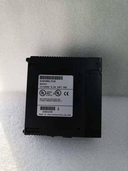
GE IC693MDL753
Real-World Applications
Legacy Equipment Retrofit with Existing PNP Sensors
In an automotive stamping plant upgrade, the IC693MDL753 retains the original PNP proximity sensors installed in the 1990s rather than replacing hundreds of sensors. The module’s negative logic configuration directly interfaces with the legacy PNP outputs, allowing the new GE 90-30 PLC to read limit switch and sensor data without sensor replacement. The 10ms filter setting eliminates false triggers from contact bounce on mechanical limit switches in the high-vibration press environment. Input states map directly to interlock logic—if any critical position sensor does not confirm the die is clear, the PLC prevents the press from initiating the stroke, maintaining the original safety logic architecture.
Plastic Injection Molding Machine Monitoring
In injection molding machines, the IC693MDL753 monitors up to 32 PNP proximity sensors detecting mold position, ejector status, hopper level, and safety gate position. The module’s sourcing output capability matches the PNP sensors commonly used in molding machines from the 2000s. The 5ms filter setting balances response speed with noise immunity in the electrically noisy environment near hydraulic pumps and heater bands. The per-point LED indicators allow rapid troubleshooting—technicians can visually identify which safety gate or mold position sensor is causing a machine 终止 without connecting to the PLC. Input consolidation into a single 32-point module reduces wiring complexity in the crowded machine control cabinet.
High-Frequency Troubleshooting FAQ
The primary difference is logic configuration: uses negative logic (sourcing outputs), while IC693MDL752 uses positive logic (sinking inputs). Functionally, both modules are identical—32 input points, 24V DC, configurable filters, identical response times. The choice depends on your field device output type. Use for PNP sensors or sourcing outputs; use IC693MDL752 for NPN sensors or sinking inputs. Mixing sensors on a single module is not recommended—mismatching logic types will cause some inputs to never turn ON regardless of field device state.
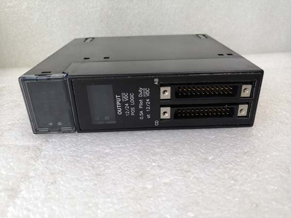
PNP sensors (sourcing outputs) connect directly to the . Connect the sensor output (brown wire for 3-wire sensors) to the desired input terminal on the . Connect the sensor negative (blue wire) to the PLC 0V reference (not the module common). Connect the module common terminal to +24V. When the sensor activates, it sources +24V to the input terminal, completing the circuit through the module to +24V common, turning the input ON. Verify polarity carefully—reversed connections will not damage the sensor but will prevent the input from functioning.
No, NPN sensors (sinking outputs) are not directly compatible with the ‘s sourcing output configuration. NPN sensors connect their output to 0V when activated, but the expects +24V at the input terminal to turn ON. To use NPN sensors with this module, you need an external signal inverter or relay to invert the signal. Alternatively, replace the NPN sensors with PNP sensors, or use the IC693MDL752 positive logic module designed for NPN devices. Never attempt to modify the module’s internal circuitry to accommodate NPN sensors.
Why do all inputs read OFF in the PLC even though LEDs are ON?
If front-panel LEDs indicate inputs are ON but the PLC reads all inputs as OFF, this indicates a backplane communication failure between the module and CPU. Possible causes include a faulty backplane connection, incorrect slot configuration in the PLC program, or module firmware mismatch. Power-cycle the rack and verify the module is recognized in the hardware configuration. If the issue persists, try the module in a different slot to isolate whether the problem is the module or the backplane. Also check the CPU’s I/O scan—if the CPU is in a fault state or I/O updates are disabled, input states will not update regardless of LED indication.
GE IC693MDL753
Commercial Availability & Pricing
Please note: The listed price is not the actual final price. It is for reference only and is subject to appropriate negotiation based on current market conditions, quantity, and availability.


