
Description
System Architecture & Operational Principle
The IC693MDL752 occupies a single slot on the GE 90-30 universal backplane, functioning as a discrete input interface at Level 1 of the Purdue Model (Basic Control). It receives 24V DC signals from field devices (sourcing outputs such as NPN proximity sensors, limit switches with PNP outputs, or PLC output modules) and converts these signals into logic levels readable by the CPU. Upstream, the CPU reads the input state via %I memory mapping during each scan; downstream, the module provides electrical isolation and filtering to prevent false triggering from signal noise or contact bounce.
The module’s architectural advantage lies in its configurable input filtering—engineers can select 1ms, 5ms, or 10ms filter times per point or per group (depending on configuration), allowing the same module to handle both fast-response applications (high-speed counter inputs, photoelectric sensors on conveyors) and noisy environments (vibration-heavy machinery with contact bounce). The positive logic configuration matches most modern field devices with sourcing outputs, simplifying wiring in new installations. Each input point is optically isolated from the backplane, protecting the CPU from field voltage transients and ground faults.
IC693MDL752
Core Technical Specifications
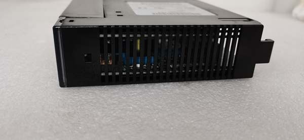
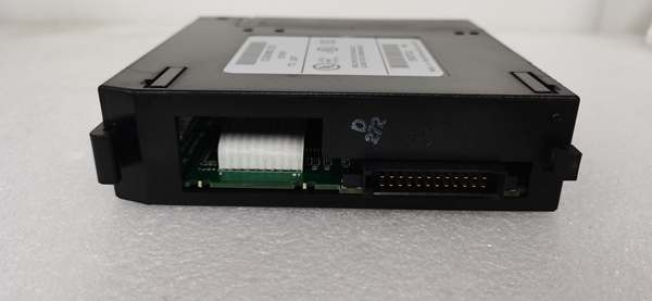
- Physical Interface: 40-pin terminal block (2 connectors, 16 points each) or front-facing removable terminal block option
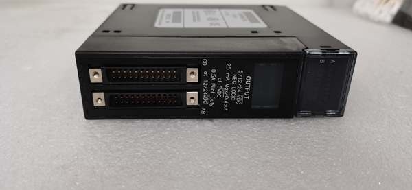
- Input Type: 32-point discrete input, 24V DC, positive logic (sinking inputs)
- Input Voltage Range: 15-30V DC (nominal 24V DC)
- Input Current: 7mA per point at 24V DC
- Input Filter Config: Selectable 1ms, 5ms, or 10ms per point group (configurable via software)
- Isolation: 1500V RMS optical isolation between field side and backplane
- Backplane Current Draw: Approximately 420mA @ 5V DC
- Response Time: 1-10ms (depending on filter setting; typical 1ms with filter disabled)
- LED Indicators: Individual LEDs per input point (ON when input energized) plus module status LEDs
- Environmental: Operating temperature 0°C to 60°C (32°F to 140°F), humidity 5-95% non-condensing
- Terminal Block: 40-pin plug-in terminal block, supports wire gauges 22-14 AWG
- Field Wiring: Positive logic—field device sourcing to input terminal, common terminal to 0V DC
- Diagnostic Capabilities: No onboard diagnostics beyond LED indication (discrete module, not intelligent)
Customer Value & Operational Benefits
Configurable Filtering Reduces False Triggers in Noisy Environments
The IC693MDL752’s selectable input filter times (1ms, 5ms, 10ms) allow engineers to match the module’s response characteristics to the electrical environment and application requirements. In facilities with heavy EMI from VFDs or welding operations, setting the filter to 10ms eliminates false triggering from noise spikes without sacrificing performance on slow-acting devices (limit switches, pressure switches). Conversely, for high-speed applications (conveyor photoeyes, encoder pulse inputs), the 1ms filter ensures rapid response. This flexibility eliminates the need for external filter modules or signal conditioners, reducing hardware cost and cabinet space requirements while improving reliability.
32-Point Density Maximizes Cabinet Space Efficiency
With 32 input points in a single slot, the IC693MDL752 reduces the number of I/O modules required for applications with high discrete point counts (e.g., large conveyor systems, assembly lines with numerous sensors). Each 32-point module replaces two 16-point modules, freeing backplane slots for other module types or reducing the physical rack size. In space-constrained installations (marine control panels, skid-mounted equipment), this density is critical—it allows more I/O capacity per cabinet footprint without sacrificing individual point indication. The per-point LED status indicators provide fast visual troubleshooting without the need for a laptop or multimeter.
Positive Logic Simplifies Modern Field Device Integration
The IC693MDL752 uses positive logic (sinking inputs), matching the output configuration of most modern field devices—NPN proximity sensors, PNP limit switches, and sourcing PLC outputs. This wiring scheme aligns with current industry practice, reducing wiring errors for technicians accustomed to modern sensor technology. Unlike negative logic modules that require careful attention to common terminal polarity, positive logic simplifies installation and commissioning, especially in retrofit projects where legacy negative logic modules are being replaced with modern equipment. Reduced wiring complexity directly translates to lower commissioning time and fewer connection errors during startup.
IC693MDL752
Field Engineer’s Notes (From the Trenches)
Here’s a gotcha that’s wasted more hours than I care to admit: the IC693MDL752’s backplane current draw is approximately 420mA at 5V DC—higher than many techs expect for a discrete input module. I’ve seen fully loaded 10-slot racks with multiple IC693MDL752 modules and analog output modules where the 5V power supply was running at 85% capacity before adding another 32-point input module pushed it into brownout territory. The symptoms? Intermittent input flickering, random CPU resets, and phantom faults that disappear when you remove a module. The fix? Always calculate your total backplane current before installation. Each draws 420mA, so four modules alone consume 1.68A. Combine that with analog modules and a CPU, and you’ll easily exceed a 3A power supply. Also, pay attention to input filter configuration—some techs leave filters at the default 10ms setting for all inputs, then wonder why high-speed photoeyes on a packaging line miss fast-moving products. Configure 1ms filters for high-speed inputs (conveyor photoeyes, encoder pulses) and 5-10ms for noisy, slow-responding devices (vibration-prone limit switches). Finally, verify your field device polarity—positive logic means the field device sources 24V to the input terminal, and the input common connects to 0V. I’ve seen techs wire NPN sensors backward (output to 0V), which causes the input LED to flicker erratically or never turn on at all. Always check the sensor’s output type (NPN vs. PNP) before wiring.
Real-World Applications
Large Conveyor System with Multiple Photoelectric Sensors
In distribution center sorting systems, the monitors up to 32 photoelectric sensors along conveyor divert lanes, package presence zones, and accumulation areas. The module’s configurable input filters allow mixed-signal environments: 1ms filters for high-speed divert photoeyes detecting packages at 600 fpm, and 10ms filters for zone presence sensors in noisy areas near sorters with high EMI. Positive logic wiring matches the NPN photoelectric sensors commonly used in material handling, simplifying installation. The per-point LED indicators allow rapid troubleshooting—technicians can visually identify which sensor triggered a divert fault without connecting to the PLC programming software.
Assembly Line Monitoring with Multiple Limit Switches
In automotive assembly plants, the monitors 32 limit switches detecting fixture positions, clamping mechanisms, and tooling presence. The 10ms filter setting eliminates false triggers from contact bounce on mechanical limit switches in vibration-heavy welding environments. The module’s 32-point density allows all fixture monitoring sensors for a single assembly station to be consolidated into one module, reducing wiring complexity in crowded robotic workcells. Input states map directly to %I memory for interlock logic—if any fixture is not in the correct position, the PLC prevents the welding robot from initiating the weld sequence, ensuring operator safety and preventing equipment damage.
High-Frequency Troubleshooting FAQ
Input filter times are configured in the PLC configuration software (LogicMaster 90-30 or Proficy Machine Edition) within the hardware configuration for the module. Filter settings can be configured per point group (typically 8 or 16 points per group) with options for 1ms, 5ms, or 10ms. After configuration changes, you must download the configuration to the CPU and power-cycle the rack for the changes to take effect. Verify filter settings by testing response time—apply a known input signal and observe the LED response or %I state update timing. If inputs appear delayed, increase the filter; if they miss fast signals, decrease the filter.
What causes input LEDs to flicker even when the field device is solidly ON?
LED flickering on an input that should be solidly ON typically indicates a weak input signal, marginal voltage, or electrical noise. Measure the input voltage at the terminal block—if it’s below 15V DC, the input is below the guaranteed ON threshold. Common causes include long cable runs with voltage drop, undersized wire gauge, or a field device with degraded sourcing capability. If voltage is within range (24V DC), suspect EMI or ground loops—route input cables away from VFD output cables and ensure the common terminal is properly referenced to the PLC 0V. Adding a 10ms filter can mask the symptom, but the root cause is usually electrical noise or a marginal signal source.
No, the is a positive logic (sinking input) module designed for sourcing field devices (PNP sensors, sourcing PLC outputs). NPN sensors (sinking outputs) cannot directly connect to this module—they would require the input common to be connected to +24V, which is incompatible with the module’s internal circuitry. To mix NPN and PNP sensors, use separate input modules or install an external signal conditioner to invert the NPN output. Always verify the sensor’s output type before wiring—NPN sensors have their output transistor connecting to 0V when ON, while PNP sensors connect to +24V when ON.
Why do I see input state changes in the PLC that don’t match the LED indicator?
If the PLC input state (%I) shows ON but the front-panel LED is OFF, or vice versa, this indicates a communication issue between the module and the CPU, not a field wiring problem. Possible causes include backplane communication errors, module firmware mismatch, or corrupted configuration. Check the module’s status LEDs—if the module shows a FAULT or COMM error, power-cycle the rack. If the issue persists, reconfigure the module in the hardware configuration and download again. This discrepancy can also occur if the input filter is set longer than the PLC scan time—the LED reflects the actual input state, but the CPU may read an outdated state due to filter delay. Ensure filter settings are appropriate for your application.
Commercial Availability & Pricing
Please note: The listed price is not the actual final price. It is for reference only and is subject to appropriate negotiation based on current market conditions, quantity, and availability.


