
Description
Hard-Numbers: Technical Specifications
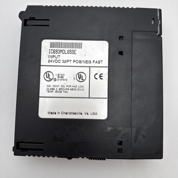
- Module Type: 24VDC Positive/Negative Logic Input Module
- Series: GE Fanuc Series 90-30
- Number of Inputs: 32 discrete inputs
- Input Grouping: 4 isolated groups of 8 inputs each
- Rated Voltage: 24 volts DC
- Input Voltage Range: 0 to 30 volts DC
- On-State Voltage: 11.5 to 30 volts DC
- Off-State Voltage: 0 to 5 volts DC
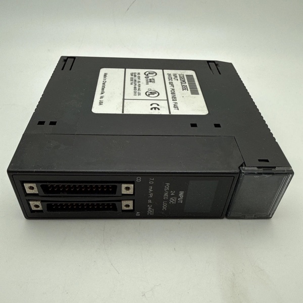
- Input Current: 7.0 mA (typical ON current @ 24 VDC)
- On-State Current: 3.2 mA (minimum)
- Off-State Current: 1.1 mA (maximum)
- Response Time (ON): 0.5 ms to 2 ms (selectable)
- Response Time (OFF): 0.5 ms to 2 ms (selectable)
- Isolation Rating: 1500 volts between field side and logic side, 250 volts between groups
- Connector Type: Two male 24-pin Fujitsu connectors (FCN-365P024-AU)
- Compatible Cables: IC693CBL327 (for groups A/B), IC693CBL328 (for groups C/D)
- Internal Power Consumption: 195 mA maximum from +5V bus on backplane; 224 mA typical from isolated +24V bus or user input supply
- Operating Temperature: 0°C to 60°C (32°F to 140°F)
- Storage Temperature: -40°C to 85°C (-40°F to 185°F)
- LED Indicators: Individual ON/OFF status LEDs for all 32 points (A1-A8, B1-B8, C1-C8, D1-D8)
- Logic Type: Configurable for positive or negative logic
- Mounting: Single slot, fits any I/O slot on 5-slot or 10-slot baseplate
- Enclosure Rating: Open enclosure (intended for cabinet-mounted use only)
- Certifications: CE, cULus

IC693MDL655E
The Real-World Problem It Solves
This module provides high-density digital input capability with optical isolation, eliminating the need for multiple lower-density modules and protecting the PLC from ground loops, voltage transients, and electrical noise commonly encountered in industrial environments. Its configurable positive/negative logic flexibility accommodates various sensor types without additional signal conditioning hardware.
Where you’ll typically find it:
- Conveyor systems monitoring limit switches and position sensors
- Assembly line push button stations and safety interlocks
- Process control equipment status monitoring (valve position, level switches)
Bottom line: It’s your workhorse digital input module for 24VDC applications, delivering 32 isolated inputs with fast response and robust protection for field signal monitoring.
Hardware Architecture & Under-the-Hood Logic
This module contains 32 individual input circuits with opto-couplers providing galvanic isolation between field wiring and the PLC backplane. Inputs are organized in four isolated groups of 8 points each, with each group sharing a common connection point.
Signal flow breakdown:
- Field device (sensor/switch) applies 24VDC signal to input terminal
- Input signal passes through protection circuitry (voltage clamping, current limiting)
- Opto-coupler provides isolation between field side and logic side
- Isolated signal feeds to input detection circuitry
- Microprocessor evaluates signal state against configurable logic (positive/negative)
- Valid signal state stored in module’s dual-port memory
- PLC CPU reads input state from dual-port memory during scan cycle
- Individual LED drivers activate corresponding status indicators for visual verification
- Internal diagnostic circuits monitor for overvoltage, undervoltage, and short-circuit conditions
- Diagnostic information reported to CPU for alarming and fault handling
IC693MDL655E
Field Service Pitfalls: What Rookies Get Wrong
Mixing Connector AssignmentsNew technicians swap cables between connectors, incorrectly wiring groups C/D to the A/B connector and vice versa, causing input mapping errors in the PLC program.
- Field Rule: Right-hand connector (from front view) is for groups A and B. Left-hand connector is for groups C and D. Verify cable part numbers (IC693CBL327 vs IC693CBL328) and label connections during installation.
Positive vs Negative Logic ConfusionEngineers configure sensors as PNP but set module for negative logic (or vice versa), causing all inputs to appear OFF when devices are actually ON.
- Field Rule: Verify sensor output type (PNP = positive logic, NPN = negative logic). Match module configuration to field device type. Test with known-good input before commissioning.
Exceeding Group Current LimitsMaintenance teams connect more than 8 inputs to a single group’s common, exceeding current capacity and causing input failure or inaccuracy.
- Field Rule: Each group supports maximum of 8 inputs sharing a common. Never exceed 8 inputs per group common. Calculate total current draw per group during design to stay within limits.
Ignoring Response Time ConfigurationTechs leave factory default response times, which may be too slow for high-speed applications causing missed signals or false triggering.
- Field Rule: Configure response time (0.5ms, 1ms, 2ms, 5ms, 10ms, 50ms, 100ms) based on application requirements. High-speed counting requires 0.5ms; general machinery typically uses 2-10ms.
Poor Grounding PracticesInstallers ground field device shields at multiple points, creating ground loops that cause erratic input behavior or phantom inputs.
- Field Rule: Ground shield wire at PLC cabinet only. Float shield at field device end when possible. Use single-point grounding to prevent ground loops, especially in long cable runs.
Missing Cable FerritesRookies install pre-wired cables without adding ferrite cores near the module, allowing EMI/RFI interference to trigger false inputs.
- Field Rule: Install ferrite cores on input cables near module connectors. Route input cables separately from power cables (>12 inches separation) to minimize electromagnetic interference.
Forgetting Isolated 24V SupplyTeams power inputs from unregulated supplies sharing ground with VFD outputs, causing voltage spikes that damage opto-couplers.
- Field Rule: Use isolated +24VDC power supply for field inputs. Do not share ground reference with output power supplies. Use the module’s isolated 24V supply capability if available.
LED Indicator Blind TrustNew techs assume LED indicators always reflect actual PLC input state, not realizing LEDs show field device status only, not backplane communication health.
- Field Rule: Verify both field device status (LEDs on module) AND PLC input table status during troubleshooting. LED ON + PLC OFF = wiring/connection issue. LED OFF + PLC ON = programming/configuration issue.
Please note: The listed price is for reference only and is not binding. Final pricing and terms are subject to negotiation based on current market conditions and availability.


