
Description
Hard-Numbers: Technical Specifications
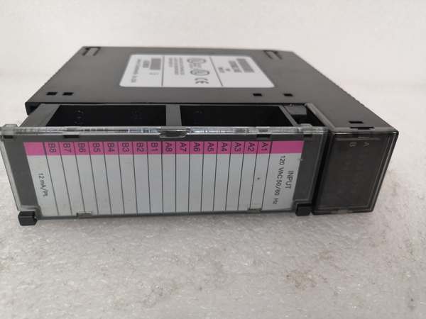
- Input Voltage Range: 0-132VAC (50/60 Hz)
- Nominal Input Voltage: 120VAC
- Input Current per Point: 12 mA typical at 120VAC
- On-State Voltage Drop: 1.5 VAC typical
- Off-State Leakage Current: 2.5 mA maximum at 132VAC
- Input Impedance: 10K ohms typical
- Response Time: 15 ms typical (ON), 25 ms typical (OFF)
- Isolation: 1500 VAC optical isolation between inputs and backplane
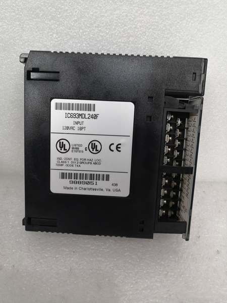
- Points per Module: 16 (single group)
- Backplane Current Draw: 90 mA @ +5 VDC
- Terminal Block: Removable 20-position terminal block
- LED Indicators: 16 individual green LEDs (one per input point)
- Operating Temperature: 0°C to 60°C (32°F to 140°F)
- Fusing Required: External fuse recommended per module (typically 2A fast-acting)
- Filtering: RC snubber network on each input for noise immunity
- Wire Size: 14-22 AWG (solid or stranded)

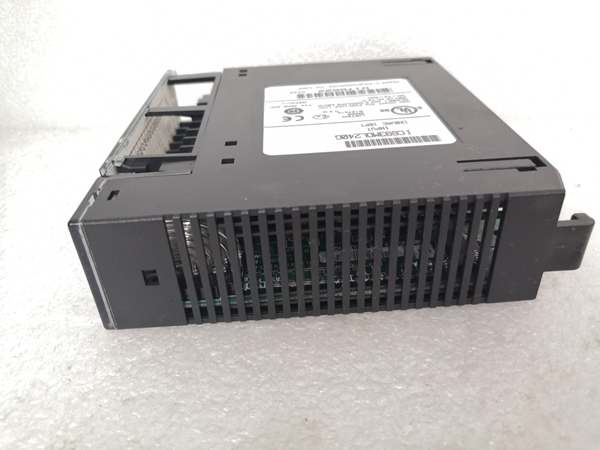
GE IC693MDL240
The Real-World Problem It Solves
Your control panel has 120VAC field devices—pushbuttons, selector switches, limit switches—and you need to bring those signals into your Series 90-30 PLC. The MDL240G provides 16 isolated input channels with individual green LED indicators that are easily visible in bright panel environments. The green LEDs provide clear, high-contrast status indication without requiring programming software or HMI access. You terminate all 16 field devices at one module, and the PLC reads the status through the backplane.
Where you’ll typically find it:
- Motor Control Centers: MCC buckets with local 120VAC control devices—start/终止 pushbuttons, selector switches, pilot lights—that need PLC monitoring and clear LED visibility in brightly lit MCC compartments
- Machine Control Panels: CNC machines, packaging equipment, and assembly machinery with 120VAC operator interface devices and limit switches where green LED status must be visible at a glance
- Process Control Skids: Pump and valve control panels with 120VAC pushbuttons, selector switches, and local indicating lights requiring PLC integration and high-contrast status indication
Bottom line: It’s the MDL240 with green LEDs—same 120VAC 16-point input functionality, but green LEDs provide enhanced visibility in bright industrial environments and offer color differentiation from other LED colors in your panel.
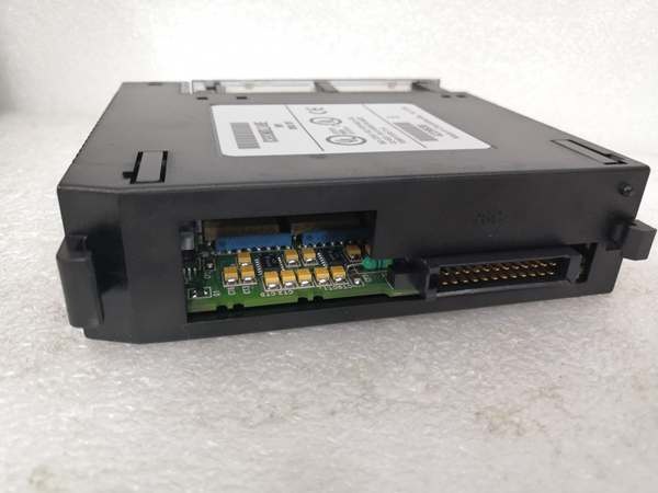
Hardware Architecture & Under-the-Hood Logic
The IC693MDL240G operates identically to the base IC693MDL240 in terms of input circuitry, isolation, filtering, and backplane communication. The only difference is the LED indicator color—MDL240G uses green LEDs instead of the standard red LEDs found on MDL240. Internally, the input circuits, optocouplers, RC filtering, and terminal block connections are identical. The green LED in each input circuit is wired in parallel with the optocoupler LED and provides visual indication when AC voltage is present at the input. Green LEDs offer better visibility in brightly lit environments and provide color coding for panel organization.
-
Input Circuit Design (Identical to MDL240): Each of the 16 inputs has the same circuit architecture as the base MDL240. Field voltage (0-132VAC) connects through the terminal block to a current-limiting resistor and RC filter network. The filtered AC signal drives an optocoupler LED. The optocoupler output transistor connects to the backplane logic circuitry, providing galvanic isolation. The green status LED replaces the red LED but functions identically.
-
AC Voltage Detection (Identical to MDL240): The input circuit detects AC voltage presence using the same rectification and filtering as MDL240. The RC network smooths the AC waveform and provides noise immunity. The optocoupler responds to the rectified DC level. The green LED illuminates when sustained AC voltage is present and remains dark when voltage is absent.
-
Optical Isolation (Identical to MDL240): The optocoupler provides 1500 VAC isolation between the field voltage side and the PLC backplane side. Isolation characteristics are identical to MDL240—green LED color has no effect on isolation performance. Each input is isolated from the backplane, and inputs share a common return on the field side.
-
Green LED Status Indication: The green LED in each input circuit provides visual indication of input state. Green LEDs offer higher brightness and better contrast in brightly lit environments compared to red LEDs. Green color also provides panel organization capability—you can use green for inputs, red for faults, amber for outputs, creating a visual color-coded system.
-
Backplane Communication (Identical to MDL240): The module communicates input status to the Series 90-30 CPU via the rack backplane exactly like MDL240. Input states are mapped to %I addresses in the PLC program. No special programming or configuration is required for MDL240G—plug and play replacement for MDL240 in most applications.
-
Input Filtering and Response Time (Identical to MDL240): The RC filter network provides the same 15 ms turn-ON and 25 ms turn-OFF response time as MDL240. Filtering prevents false triggering from electrical noise. Green LED color does not affect response time or filtering characteristics.
-
Current Limiting and Protection (Identical to MDL240): Each input circuit includes the same current-limiting resistance and protection diodes as MDL240. External fusing requirements are identical (2A fast-acting recommended). Green LED color does not affect protection circuitry or current requirements.
-
Removable Terminal Block (Identical to MDL240): The module uses the same removable 20-position terminal block as MDL240. Terminal block compatibility allows MDL240G to replace MDL240 without rewiring. Terminal block accepts 14-22 AWG solid or stranded wire with screw termination.
-
Common Return Connection (Identical to MDL240): All 16 inputs share a common return (typically the 120VAC neutral connection) on the terminal block, identical to MDL240. Wiring requirements and grounding considerations are the same—green LED color does not affect electrical connections.
-
Module Health Monitoring (Identical to MDL240): The module monitors internal health and reports status to the CPU through backplane registers, identical to MDL240. Diagnostic information and module health reporting are unaffected by LED color. The CPU cannot distinguish between MDL240 and MDL240G through backplane communication.
GE IC693MDL240
Field Service Pitfalls: What Rookies Get Wrong
Assuming green LED indicates different electrical characteristics
You think MDL240G has different input specs because it has green LEDs. You hesitate to mix MDL240 and MDL240G in the same rack or replace MDL240 with MDL240G unnecessarily.
Field Rule: MDL240 and MDL240G are electrically identical. The only difference is LED color—green versus red. Input voltage range, current, response time, isolation, and all other specifications are the same. MDL240G can replace MDL240 and vice versa. Don’t let LED color create false electrical distinctions—they’re functionally interchangeable.
Mixing LED colors for no reason
You install a mix of MDL240 (red LEDs) and MDL240G (green LEDs) in the same panel without a plan. Operators are confused by inconsistent LED colors, and troubleshooting takes longer because different modules use different colors for the same function.
Field Rule: Standardize on one LED color per application or use color intentionally for panel organization. If you use both MDL240 and MDL240G, establish a clear scheme—perhaps MDL240G for operator inputs (pushbuttons, selectors) and MDL240 for limit switches and sensors. Document the color scheme and train operators. Inconsistent LED colors without logic create confusion.
Forgetting external fusing because “it’s a different model”
You treat MDL240G as a completely different module and skip external fusing because you’re unfamiliar with its requirements. A field wiring short occurs, and the module input circuit burns out.
Field Rule: MDL240G requires the same external fusing as MDL240. Install a 2A fast-acting fuse per module on the 120VAC supply. LED color does not change fusing requirements. External fusing protects the module input circuits from overcurrent damage. Never connect directly to an unfused AC source, regardless of LED color.
Improper grounding causing false triggering (same issue as MDL240)
You connect field devices to different ground references than the module return. Ground loops cause inputs to trigger randomly, and you assume the green LED module is defective.
Field Rule: Grounding requirements for MDL240G are identical to MDL240. Ensure all field devices share a common ground reference with the module return connection. Green LED color does not change grounding requirements or noise immunity. Ground loops cause erratic input behavior regardless of LED color—establish a single-point ground reference.
Wiring 24VDC to MDL240G (same error as MDL240)
You try to connect a 24VDC proximity switch to the MDL240G. The DC voltage doesn’t properly drive the AC input circuit, and the green LED doesn’t illuminate properly.
Field Rule: MDL240G is designed for 120VAC inputs only, identical to MDL240. Use 24VDC input modules for DC field devices. Green LED color does not enable DC operation—this is still an AC-only input module. Match the input module voltage rating to your field device voltage.
Neglecting torque specifications on terminal block (same as MDL240)
You tighten terminal screws by feel without a torque screwdriver on your MDL240G. Connections loosen over time, and you experience intermittent input faults.
Field Rule: Use a torque screwdriver and follow the same torque specifications for MDL240G as MDL240 (typically 6-8 in-lbs for GE terminal blocks). Green LED color does not change terminal block specifications or torque requirements. Proper torque ensures secure connections. Torque every connection systematically.
Ignoring input response time limitations (same as MDL240)
You try to use the MDL240G for high-speed pulse counting. The 15-25 ms response time is too slow, and you miss counts.
Field Rule: MDL240G has the same 15-25 ms response time as MDL240. Green LED color does not affect response time. For high-speed applications, use high-speed counter modules or specialized input modules with microsecond response times. Don’t expect general-purpose AC input modules with green LEDs to handle high-speed signals.
Overlooking module replacement with power applied (same as MDL240)
You try to replace the MDL240G while the rack is powered. The backplane communication is interrupted, the CPU faults, and you may damage the module.
Field Rule: Always power down the rack before replacing MDL240G, identical to MDL240. LED color does not enable hot-swapping capability. While some modules support hot insertion, the MDL240G is not rated for hot swap. Follow proper power-down procedures for module replacement.
Using green LEDs as the sole troubleshooting indicator
You rely entirely on the green LED status and don’t verify input state in programming software. A green LED illuminates but the PLC doesn’t see the input because of a backplane communication issue. You assume the field wiring is good based on the LED.
Field Rule: Green LED status indicates voltage at the input terminal, not PLC recognition. Always verify input state in programming software (%I addresses) when troubleshooting. The green LED confirms field voltage presence, but backplane communication issues can still prevent the CPU from seeing the input. Use both LED indication and software verification for complete troubleshooting.
Commercial Availability & Pricing Note
Please note: The listed price is for reference only and is not binding. Final pricing and terms are subject to negotiation based on current market conditions and availability.


