
Description
System Architecture & Operational Principle
The IC693MAR590 occupies a single slot on the GE 90-30 universal backplane, functioning as a dedicated motion controller at Level 1 of the Purdue Model (Basic Control). It receives high-level motion commands (move profiles, cam tables, position setpoints) from the CPU via shared memory mapping (%R registers) and executes independent position/velocity loops without continuous CPU intervention, freeing the main processor for logic and sequencing tasks. Upstream, the CPU triggers motion programs and monitors status via ladder logic; downstream, the module outputs drive signals to servo amplifiers (±10V analog or pulse/direction) while closing the position loop using quadrature encoder feedback from motors or external encoders.
The module’s inherent advantage lies in its deterministic execution—the motion control loop runs independently of PLC scan time, ensuring consistent servo performance regardless of main CPU load. It supports electronic gearing and camming between axes, enabling synchronized multi-axis motion (e.g., conveyor tracking, flying cutoffs) that would be impossible with standard I/O modules. The IC693MAR590 communicates with GE S2P servo drives or third-party amplifiers, making it suitable for both GE-integrated motion systems and retrofit applications.
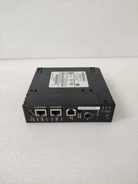
GE IC693CPU374
Core Technical Specifications
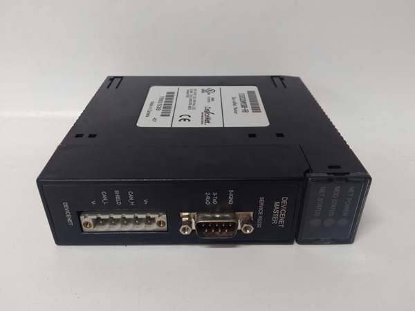
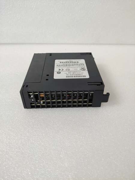
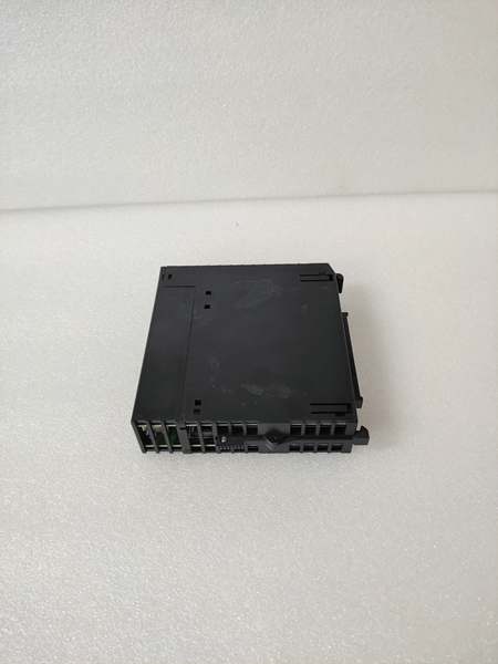
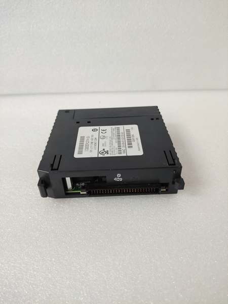
- Physical Interface: 2 high-density 50-pin SCSI-style connectors for drive I/O and feedback, single-slot width module
- Axis Capacity: Up to 4 independent servo/stepper axes per module
- Drive Interface: ±10V analog output (12-bit resolution) OR pulse/direction (programmable frequency up to 2 MHz)
- Encoder Input: Quadrature encoder input, up to 20 MHz per axis, supports differential line driver or open-collector
- Feedback Types: Quadrature encoder, resolver (with external interface), or simulated feedback
- Control Modes: Position, Velocity, Torque, Electronic Gearing, Electronic Camming
- Programming Software: LogicMaster 90-30 Motion Developer or Proficy Machine Edition Motion
- Memory: 128K user memory for motion programs, cam tables, and parameters
- Backplane Current Draw: Approximately 800mA @ 5V DC (higher than standard I/O due to motion processing)
- Operating Temperature: 0°C to 60°C (32°F to 140°F)
- Environmental: NEMA 12 enclosure rating when properly installed in industrial cabinet
- Diagnostics: Front-panel LEDs per axis (RUN, FAULT, ENABLE) plus module-level status
- Update Rate: 250 µs position loop update rate per axis (deterministic)
Customer Value & Operational Benefits
Deterministic Motion Performance Independent of PLC Scan
The IC693MAR590 executes motion control loops with a fixed 250 µs update rate, completely independent of the main CPU’s scan time. In applications where PLC scan time varies due to complex logic or communication overhead (typically 10-50ms), standard I/O-based motion would exhibit inconsistent servo performance and position lag. This module eliminates that variability, ensuring smooth, precise motion regardless of PLC load—critical for packaging machinery, cutting operations, and conveyor tracking where timing consistency directly impacts product quality.
Reduced Programming Complexity with Built-in Motion Functions
The module includes pre-programmed motion primitives—homing sequences, electronic camming, gear ratios, and position/velocity profiles—that eliminate the need for custom ladder logic to implement basic motion functions. Engineers configure motion parameters via a dedicated motion development environment rather than writing complex position calculation routines in ladder logic. This reduces development time by 40-60% compared to implementing motion control with standard I/O modules, and the pre-verified motion functions reduce commissioning risk and debugging effort.
Multi-Axis Synchronization for Complex Motion Profiles
Electronic camming and gearing between up to 4 axes enables synchronized motion profiles that would be impossible with independent servo drives. For example, a flying cutoff saw can synchronize its blade speed to a moving conveyor’s position, ensuring perpendicular cuts regardless of line speed variation. The module handles the real-time position synchronization calculations internally, outputting coordinated drive signals to each axis. This capability eliminates the need for external motion controllers or PLC-based position interpolation, reducing hardware cost and system complexity while improving synchronization accuracy to within ±1 encoder count.
GE IC693CPU374
Field Engineer’s Notes (From the Trenches)
Here’s a gotcha that’s caused me sleepless nights: the IC693MAR590’s backplane current draw is approximately 800mA at 5V—that’s more than double a standard I/O module. I’ve seen techs plug this module into a fully loaded 10-slot rack with multiple analog modules and wonder why the rack keeps resetting at random intervals. The 5V power supply was marginally sized before adding the motion module, and the additional 800mA pushed it over the edge during simultaneous axis motion. The fix? Calculate your total backplane current before installation. Each axis in motion increases the module’s current draw, so worst-case calculation assumes all 4 axes active. Also, pay attention to encoder cable routing—I’ve chased phantom following errors for days only to discover the encoder cable was run parallel to VFD output cables. The induced noise caused erratic encoder counts, and the servo would hunt around the target position. Run encoder cables in separate conduit with shield grounded at the controller cabinet only. Finally, verify your drive interface matches the module configuration—some techs set the module for ±10V analog but connect pulse/direction outputs, resulting in zero servo movement. The front-panel LEDs won’t show a fault for this mismatch; you just get no motion. Always cross-check the drive’s input mode against the module’s configuration jumper/software setting before power-up.
Real-World Applications
Flying Cutoff Saw in Lumber Processing
In sawmills, the IC693MAR590 controls a flying cutoff saw that cuts lumber to length while the material is moving on a high-speed conveyor. The module reads encoder feedback from the conveyor to determine material position and velocity, then executes an electronic cam profile to synchronize the saw blade rotation and feed axis with the moving lumber. The saw blade accelerates to match conveyor speed, cuts perpendicular to the material direction, and decelerates for the next cycle. The module’s 250 µs update rate ensures precise synchronization even at conveyor speeds exceeding 500 fpm, preventing crooked cuts and material waste.
Multi-Axis Pick-and-Place Robot in Food Packaging
In food packaging lines, the IC693MAR590 controls a 3-axis pick-and-place robot (X, Y, Z axes) that transfers products from conveyor belts to packaging trays. The module executes coordinated motion profiles to accelerate and decelerate all axes simultaneously, optimizing cycle time while minimizing vibration. Electronic camming synchronizes the Z-axis vertical motion with the X-Y horizontal motion, ensuring smooth pickup and placement without product damage. The module’s homing sequence automatically establishes axis reference positions at startup, eliminating manual positioning adjustments during shift changes. Position loop closure is performed by the module using encoder feedback from each axis servo motor, with velocity commands sent to servo drives via ±10V analog outputs.
High-Frequency Troubleshooting FAQ
How do I reset a servo axis fault without 终止ping the entire motion system?
Use the fault reset command in the motion development software or write a specific value to the axis control word in %R memory (typically bit 5 for axis reset). The supports individual axis fault reset, allowing you to clear a fault on one axis while others continue running. However, ensure the root cause is addressed—common faults include following error, encoder loss, or overtravel. Check the module’s fault code register for specific fault details before resetting. If the fault recurs immediately, verify encoder cabling, limit switch wiring, and drive enable signals.
What does a blinking FAULT LED on a specific axis indicate?
A blinking FAULT LED on an individual axis (not the module-wide FAULT LED) typically indicates a non-critical warning such as following error approaching the threshold, minor velocity deviation, or a soft limit warning. A solid FAULT LED indicates a critical fault requiring immediate attention—encoder signal loss, overtravel, drive fault, or communication timeout. Consult the motion development software’s diagnostic window for the specific fault code and description. Blinking FAULT LEDs often precede solid faults, so investigate warnings before they escalate into hard faults.
Yes, the supports ±10V analog output or pulse/direction drive interface, making it compatible with virtually any servo drive accepting these standard command signals. Configure the drive interface in the motion development software to match your drive’s requirements (analog voltage range, pulse frequency, direction logic). Note that some drive-specific features (e.g., drive-based homing, specific commutation modes) may not be accessible through the —you’ll need to configure those parameters directly on the drive. Ensure proper ground referencing between the module and drive to avoid ground loops in analog command signals.
Why does my axis exhibit following error only during rapid moves?
Following error during rapid moves typically indicates inadequate velocity feedforward or acceleration feedforward tuning. The provides feedforward gains to anticipate the position error that occurs during acceleration/deceleration phases. Increase velocity feedforward to compensate for following error during constant velocity, and acceleration feedforward for ramp phases. Also, verify your servo drive’s velocity loop bandwidth—if the drive’s internal loop is too slow, it cannot respond quickly to the motion command’s rapid changes, causing following error. Start with feedforward gains at 50% and gradually increase while monitoring following error magnitude.
Commercial Availability & Pricing
Please note: The listed price is not the actual final price. It is for reference only and is subject to appropriate negotiation based on current market conditions, quantity, and availability.


