
Description
Hard-Numbers: Technical Specifications
- Module Type: DeviceNet Master Module
- Series: GE Fanuc Series 90-30 / PACSystems RX3i
- Communication Protocol: DeviceNet (ODVA compliant)
- Supported Data Rates: 125K, 250K, 500K Baud
- Maximum Slave Devices: 63 DeviceNet slaves
- I/O Connections: Up to 126 total connections (2 connections per slave)
- Data Transfer per Slave: 255 Input Bytes / 255 Output Bytes
- Total Data Transfer to Master: 3972 Input Bytes / 3972 Output Bytes
- Connection Types: Polled, Strobe, Cyclic, COS (Change of State)
- Advanced Features: Explicit messaging, UCMM (Unconnected Message Manager), 1 Proxy connection per slave
- Dual Mode Operation: Master and Slave simultaneously
- Module Width: Single slot
- Mounting Location: Series 90-30 main rack: Any slot except 0 and 1; RX3i main rack: Any slot except slot 0
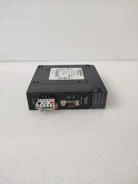
- Communication Ports: 1 DeviceNet terminal + 1 RS-232 service port (9-pin D-shell female)
- Backplane Current Draw: 450 mA at 5V DC (typical)
- External Power Requirements: 12-24V DC (positive logic)
- Number of Output Points: 32 (organized in groups of 4, 8 points per group)
- Output Current Rating: 0.5 Amps per point
- Maximum Current per Group: 4 Amps
- Maximum Current per Group Common Pin: 3 Amps
- Inrush Current: 5.4 Amps for 10 milliseconds
- ON-State Voltage Drop: 0.3V DC
- ON/OFF Response Time: 0.5 milliseconds (maximum)
- Operating Temperature: 0°C to 60°C (32°F to 140°F)
- Storage Temperature: -40°C to 85°C (-40°F to 185°F)
- Firmware Upgradeable: Yes (via RS-232 service port)
- Fault Behavior Configurable: Yes (communication loss reaction)

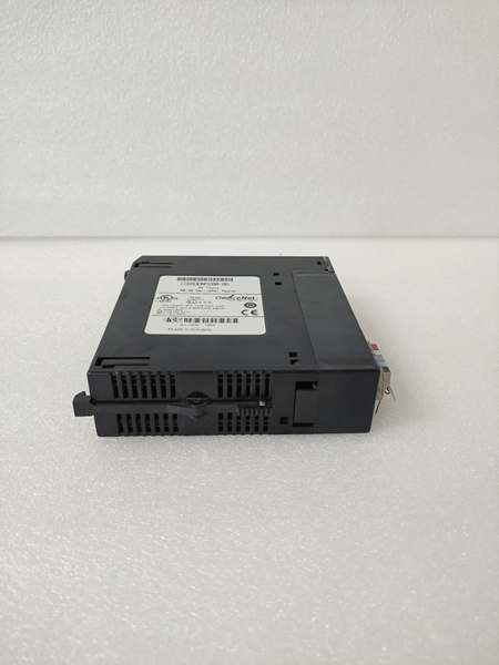
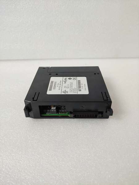
GE IC693DNM200-BD
The Real-World Problem It Solves
This module bridges the gap between Series 90-30/RX3i PLCs and DeviceNet field networks, eliminating the need for expensive gateway systems or complete PLC replacements. Its ability to operate in dual Master/Slave mode provides flexibility for hierarchical control architectures without additional hardware.
Where you’ll typically find it:
- Automotive assembly lines communicating with DeviceNet-equipped robots and sensors
- Material handling systems integrating various vendor devices on a single network
- Packaging machinery coordinating multiple DeviceNet-compatible actuators and drives
Bottom line: It’s your DeviceNet gateway for GE Series 90-30 systems, enabling seamless communication with up to 63 field devices without changing your entire PLC platform.
Hardware Architecture & Under-the-Hood Logic
The IC693DNM200-BD contains a dedicated microprocessor and dual-port memory architecture for managing DeviceNet communications independently of the PLC CPU. This offloads network processing tasks, ensuring consistent scan times even with heavy network traffic.
Signal flow breakdown:
- PLC CPU writes I/O data to module’s dual-port memory via backplane
- Module’s internal processor reads data from dual-port memory
- DeviceNet communication controller formats data for transmission per configured connection type
- Data transmitted over DeviceNet network at selected baud rate (125K/250K/500K)
- Responses received from slave devices processed and validated
- Input data written to dual-port memory for PLC CPU access
- PLC CPU reads input data from dual-port memory during scan cycle
- RS-232 service port provides diagnostics, configuration, and firmware update interface
- Fault detection logic monitors network integrity and triggers configured fault actions
- Dual Master/Slave mode enables simultaneous upstream and downstream communication
GE IC693DNM200-BD
Field Service Pitfalls: What Rookies Get Wrong
Improper Rack InstallationTechs install the module in expansion or remote racks instead of the main rack, causing communication failures.
- Field Rule: Mount this module only in the main rack. For Series 90-30, any slot except 0 and 1. For RX3i, any slot except slot 0. Never install in remote/expansion racks.
Data Rate MismatchNew engineers configure different baud rates on the module and DeviceNet slaves, resulting in complete network failure.
- Field Rule: Verify all devices on the DeviceNet network use the same baud rate. Set module to match network specification before connecting slaves. Start at 125K for initial commissioning.
Exceeding Current LimitsMaintenance teams overload output groups by drawing more than 3 Amps per common pin or 4 Amps per group, causing fuse failures or module damage.
- Field Rule: Calculate total current draw per group during design. Include inrush currents for all connected devices. Use separate DeviceNet power supplies if needed to stay within limits.
Ignoring Dual Mode ConfigurationRookies configure the module as Master-only, preventing integration with higher-level supervisory systems.
- Field Rule: Enable dual Master/Slave mode when connecting to a supervisory PLC or HMI. Configure slave communication parameters separately from master parameters for hierarchical networks.
Firmware Update FailureTechnicians interrupt firmware updates via RS-232 service port, bricking the module and requiring factory repair.
- Field Rule: Never power down during firmware updates. Use stable laptop battery power or UPS during the process. Verify RS-232 cable connections and baud rate settings before initiating updates.
Terminator Installation ErrorsInstallers forget network terminators or install them incorrectly, causing signal reflections and intermittent communication errors.
- Field Rule: Install DeviceNet terminators (121Ω) at both ends of the trunk line. Remove terminators from drop lines. Verify termination with network analyzer if issues persist.
Grounding and Shielding MistakesField technicians ground shields at both ends or fail to establish proper network ground, leading to noise and communication failures.
- Field Rule: Ground DeviceNet cable shield at the master end only. Establish a single-point network ground reference. Use star topology grounding when connecting multiple devices to prevent ground loops.
Please note: The listed price is for reference only and is not binding. Final pricing and terms are subject to negotiation based on current market conditions and availability.


