
Description
Hard-Numbers: Technical Specifications
- Protocol: DeviceNet (ODVA-compliant)
- Communication Rate: 125 Kbps, 250 Kbps, 500 Kbps (selectable via DIP switches)
- Node Capacity: Up to 63 slave nodes
- I/O Data Size: Up to 512 bytes input / 512 bytes output per scan
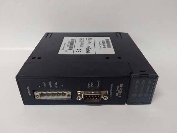
- Connector: 5-pin DeviceNet Mini-Change (M12) connector
- Network Power: 24V DC input for network power (separate from backplane power)
- Backplane Current Draw: Approximately 350mA @ 5V DC
- Operating Temperature: 0°C to 60°C (32°F to 140°F)
- Isolation: Optical isolation on DeviceNet port (500V minimum)
- LED Indicators: MOD, NET, PWR, FAULT, I/O (per configured data exchange status)
- Module Slot: Single slot width in 90-30 universal backplane
- Configuration Software: VersaPro or Proficy Machine Edition DeviceNet configuration tool
- Watchdog: Configurable watchdog timer for slave communication monitoring
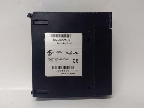
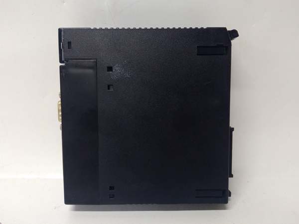
GE IC693DNM200
The Real-World Problem It Solves
This module bridges legacy GE 90-30 control systems with modern DeviceNet field networks without requiring a full PLC platform upgrade. It eliminates the need for hardwired I/O racks at distant equipment locations by enabling distributed device communication over a single twisted-pair cable.
Where you’ll typically find it:
- Conveyor systems with distributed motor starters and photoelectric sensors
- Assembly lines integrating DeviceNet-capable VFDs and valve manifolds
- Material handling facilities using DeviceNet barcode readers and pushbutton stations
Bottom line: It extends the lifespan of 90-30 systems by enabling connectivity to DeviceNet field devices while reducing complex multi-conductor cable runs.
Hardware Architecture & Under-the-Hood Logic
The IC693DNM200 plugs into the 90-30 backplane as a scanner, exchanging data with the CPU through shared memory mapping while managing DeviceNet messaging on the network side. It acts as a DeviceNet master, polling configured slave devices and mapping their I/O data into PLC registers.
- Initialization: The module reads its configuration from the CPU (stored in %L or %R memory) and establishes DeviceNet network identity.
- Network scanning: The module polls configured slave nodes based on the scheduled COS (Change of State) or polling intervals.
- Data mapping: Input data from slaves is written to mapped %I and %AI registers; output data to slaves is read from mapped %Q and %AQ registers.
- Diagnostics monitoring: The module continuously monitors node status, updating fault codes and LED indicators for communication failures.
- Watchdog action: If a slave fails to respond within the watchdog timeout, the module can optionally place its outputs into a predefined fault state.
GE IC693DNM200
Field Service Pitfalls: What Rookies Get Wrong
Network Termination Resistors
Techs leave off termination resistors at both ends of the DeviceNet trunk line, causing signal reflections that manifest as intermittent node dropouts and corrupted data. The NET LED flashes irregularly, but no specific fault code points to termination.
Field Rule:Install 121Ω termination resistors at both physical ends of the DeviceNet trunk. Only resistors—no T-connections or tees—at the endpoints. Verify with an ohmmeter: resistance between CAN-H and CAN-L should be approximately 60Ω when both resistors are installed.
Network Power Budgeting
Rookies power the DeviceNet network from the IC693DNM200’s 24V input without calculating total node current draw. Adding multiple VFDs or high-current valve manifolds overloads the network power supply, causing brownouts that drop nodes randomly during high activity.
Field Rule:Calculate total DeviceNet node current consumption (usually specified in mA per device). The module’s 24V input has limits; for networks exceeding 3A, use an external DeviceNet power supply with a separate power tap mid-trunk. Never daisy-chain power through nodes.
Configuration Data Mismatch
After replacing a module, techs download the wrong EDS file or incorrect data mapping configuration, causing the CPU to read garbage from wrong %R register addresses. The system runs but produces erratic control behavior.
Field Rule:Always verify the EDS file version matches the device revision, and document the register mapping (%I/%Q/%R addresses) before any swap. Save the configuration file (EDS+DCS) with the project name—never rely on memory alone.
Improper Grounding of DeviceNet Shield
Techs ground the DeviceNet cable shield at multiple points along the trunk, creating ground loops that induce noise on the CAN bus. This leads to sporadic COM errors and phantom fault codes that disappear only when touching the cable.
Field Rule:Ground the cable shield at exactly one point—typically at the PLC cabinet where the IC693DNM200 is located. Use shielded cable with drain wire, and connect only the drain wire to the cabinet ground bus. Leave the shield floating at all field devices and the far-end terminator.
Commercial Availability & Pricing Note
Please note: The listed price is for reference only and is not binding. Final pricing and terms are subject to negotiation based on current market conditions and availability.


