
Description
Hard-Numbers: Technical Specifications
- Network Protocol: DeviceNet (ODVA compliant)
- Network Role: Master (Scanner) / Slave (Adapter) selectable
- Bus Speed: 125 Kbps, 250 Kbps, 500 Kbps (configurable)
- Maximum Nodes: 63 nodes per network
- Maximum I/O: 512 bytes input, 512 bytes output (excludes overhead)
- Backplane Current Draw: 550 mA @ +5 VDC
- Isolation: 500 VDC optical isolation between DeviceNet network and backplane
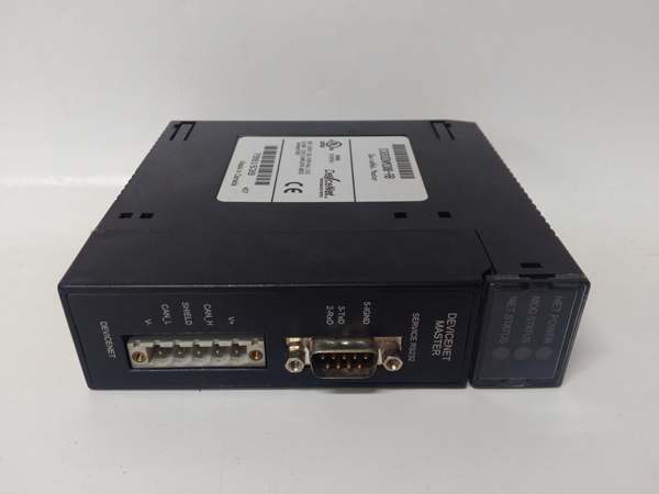
- Connector Type: 5-pin mini DeviceNet connector
- Termination: 120 ohm resistor required at both network ends
- Network Address: Rotary switch (0-63) configurable via front panel
- LED Indicators: Module OK, Network OK, Comm Activity, Fault
- Operating Temperature: 0°C to 60°C (32°F to 140°F)
- Fault Protection: Short-circuit protection on network port
- Scan Time: Deterministic scan based on DeviceNet MAC ID polling order

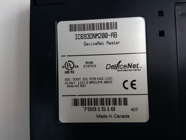
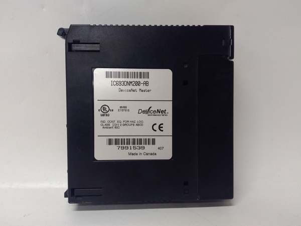
IC693DNM200
The Real-World Problem It Solves
You have a conveyor system or production line with dozens of DeviceNet-compatible drives, motor starters, and distributed I/O blocks spread across hundreds of feet, and running individual homerun cables to each device is a wiring nightmare. This module gives you a single DeviceNet trunk line that drops off at each device—drastically reducing wiring complexity, installation time, and troubleshooting effort. Your Series 90-30 PLC talks to the DNM200, and the DNM200 handles all the DeviceNet polling and data exchange.
Where you’ll typically find it:
- Conveyor and Material Handling Systems: Distribution centers and assembly lines where variable frequency drives, photo-eyes, and distributed I/O are located along long conveyor runs
- Automotive Assembly Lines: Manufacturing cells with multiple DeviceNet-enabled devices (tool changers, clamps, position sensors) networked to a central Series 90-30 controller
- Packaging Machinery: Packaging equipment with distributed I/O islands, servo drives, and operator interfaces communicating over DeviceNet
Bottom line: It’s your Series 90-30 gateway to DeviceNet—replaces hundreds of individual wires with a single 4-wire network trunk that polls up to 63 devices from one master module.
Hardware Architecture & Under-the-Hood Logic
The IC693DNM200 plugs into any Series 90-30 I/O slot and communicates with the PLC backplane via standard rack communication. The module contains a DeviceNet controller ASIC that handles all network protocol functions independently of the PLC processor. The PLC sees the DNM200 as an I/O module—input and output data is exchanged between the PLC and DNM200 through backplane communication, while the DNM200 manages DeviceNet messaging, polling, and error handling autonomously.
-
Backplane Communication: The DNM200 exchanges input and output data with the Series 90-30 CPU via the rack backplane. Input data from DeviceNet devices is mapped to %I addresses in the PLC. Output data from the PLC is mapped to %Q addresses and sent to DeviceNet devices. The CPU scans the DNM200 like any other I/O module—no special programming is required for data exchange.
-
DeviceNet Network Initialization: On power-up, the DNM200 initializes the DeviceNet controller and sends duplicate MAC ID detection messages. The module waits for its assigned MAC ID (0-63, configured via front panel rotary switch) to be verified unique. Once MAC ID is confirmed, the module sends online messages and begins scanning the network for slave devices.
-
Device Polling and Data Exchange: As the DeviceNet master, the DNM200 polls each connected slave device in sequence according to the configured polling order. For each device, the DNM200 sends explicit messages requesting input data and sends output data to the device. The polling sequence repeats continuously, ensuring deterministic data exchange based on network configuration.
-
I/O Mapping: Input data from DeviceNet devices is assembled into the DNM200’s input buffer and presented to the PLC backplane as discrete %I and analog %AI words. Output data from the PLC (%Q and %AQ) is assembled into the DNM200’s output buffer and transmitted to DeviceNet devices during polling. The mapping between DeviceNet devices and PLC addresses is configured using DeviceNet configuration software (GE Fanuc Cimplicity or third-party tools).
-
Error Handling and Fault Detection: The DNM200 monitors network health continuously. If a slave device fails to respond within the watchdog timeout, the DNM200 flags the device as offline and reports the fault via front panel LED and PLC diagnostic words. The module continues communicating with other devices—single device failures do not bring down the entire network.
-
Master/Slave Selectability: The DNM200 can operate as either a DeviceNet master (scanner) or slave (adapter), configurable via software. In slave mode, another DeviceNet master polls the DNM200, and the module acts as a bridge between DeviceNet and the Series 90-30 PLC. This configuration is useful when integrating Series 90-30 into an existing DeviceNet network controlled by another master.
-
Network Bandwidth Management: The DNM200 manages network bandwidth by controlling the polling rate and message size per device. The module calculates the required bandwidth for all configured devices and ensures it does not exceed the available bandwidth for the selected bus speed (125K, 250K, or 500K). If bandwidth is exceeded, the module reports a configuration error during initialization.
-
Optical Isolation: The DeviceNet network port is optically isolated from the backplane and PLC logic. A 500VDC isolation barrier protects the PLC and backplane from network faults, ground loops, and voltage spikes that may occur on the DeviceNet trunk line. This isolation is critical in industrial environments with long cable runs and multiple ground references.
-
Configuration Storage: DeviceNet network configuration (device list, polling order, I/O mapping, baud rate) is stored in non-volatile memory on the DNM200. Configuration is uploaded to the module via DeviceNet configuration software connected through the network or via a programming port. The module retains configuration through power cycles—re-configuration is only required when network topology changes.
-
Diagnostic Reporting: The DNM200 reports detailed diagnostic information to the PLC through diagnostic %I words. This includes device online/offline status, communication error counts, network health metrics, and module health status. PLC programs can monitor these diagnostics to trigger alarms or take corrective action when network issues occur.
IC693DNM200
Field Service Pitfalls: What Rookies Get Wrong
Forgetting termination resistors
You install the DeviceNet trunk line with nodes at both ends but no termination resistors. The network experiences intermittent communication failures, CRC errors, and devices dropping offline randomly. The DNM200 reports network faults but you can’t find the problem.
Field Rule: DeviceNet requires 120 ohm termination resistors at both physical ends of the trunk line. Without termination, signal reflections cause communication errors. Install resistors at the first and last device on the trunk. Verify resistance is approximately 60 ohms when measuring across the network (two 120 ohm resistors in parallel). No termination equals no reliable communication—always verify resistance before commissioning.
Setting duplicate MAC IDs
You configure two devices with the same MAC ID address (0-63) on the same network. Both devices detect the duplicate during initialization and refuse to come online. The DNM200 flags a duplicate MAC ID fault, but you don’t know which device is the problem.
Field Rule: Every DeviceNet device must have a unique MAC ID. Configure MAC IDs carefully using rotary switches or software configuration tools. Document MAC ID assignments for each device location. Before power-up, verify no duplicate IDs exist. If duplicate MAC ID fault occurs, disconnect devices one at a time until the fault clears—then fix the duplicate ID. Never ignore duplicate MAC ID faults—the network won’t operate with duplicates present.
Ignoring baud rate mismatches
You set the DNM200 to 500 Kbps but some field devices are still at 125 Kbps. Devices with mismatched baud rates can’t communicate or generate network errors. The DNM200 reports communication faults, but you assume it’s a cabling issue.
Field Rule: All devices on a DeviceNet network must operate at the same baud rate. Configure all devices to match the DNM200 baud rate (125K, 250K, or 500K). Verify baud rate settings before commissioning. If devices are dropping off randomly, check baud rate consistency—mixed baud rates cause communication failures. The DNM200 only communicates with devices at the configured baud rate.
Overloading the network with too many devices
You keep adding devices to the network until you hit 63 nodes. Communication becomes slow, devices timeout, and the network experiences frequent re-initializations. You’ve exceeded the available bandwidth even though you haven’t exceeded the node count.
Field Rule: Node count isn’t the only limit—bandwidth matters too. Calculate total required bandwidth for all devices at your configured baud rate. Leave 20-30% headroom for future expansion and network stability. If communication degrades after adding devices, you’ve likely exceeded bandwidth. Reduce the number of devices or increase baud rate (if cable length permits). Overloaded networks behave unpredictably—plan for bandwidth, not just nodes.
Neglecting proper cable length limits
You install DeviceNet at 500 Kbps with a 800-meter trunk line. Communication fails intermittently, devices timeout, and the DNM200 reports excessive network errors. You’ve exceeded the maximum cable length for the baud rate.
Field Rule: DeviceNet cable length depends on baud rate:
- 500 Kbps: Maximum 100 meters
- 250 Kbps: Maximum 250 meters
- 125 Kbps: Maximum 500 meters
Exceeding these limits causes signal degradation and communication failures. Use repeaters or network bridges to extend distance if needed. Design your network topology within baud rate limits—longer cables require lower baud rates.
Mixing thick and thin trunk lines without taps
You use thick trunk cable with thin drop lines but install the thin cable directly into the trunk without proper taps. The impedance mismatch causes signal reflections and communication errors. Devices connected to thin lines drop offline intermittently.
Field Rule: Use proper DeviceNet taps and connectors when transitioning from thick trunk to thin drop lines. Thick trunk cable has different impedance than thin drop cable. Taps provide impedance matching and proper signal routing. Don’t just splice thin cable into the trunk—use manufacturer-approved taps and connectors. Impedance mismatches cause network failures even with correct termination.
Forgetting to map I/O in configuration software
You physically connect devices and wire the network, but you don’t configure I/O mapping in DeviceNet configuration software. The DNM200 comes online, but data doesn’t transfer between the PLC and field devices. You assume the module is defective.
Field Rule: Physical network connectivity isn’t enough—you must configure I/O mapping in DeviceNet configuration software. Map each device’s input and output data to specific %I/%Q addresses in the PLC. Download the configuration to the DNM200 after making changes. Verify data exchange using programming software to monitor %I and %Q addresses. Unconfigured networks don’t transfer data—configure before you commission.
Overlooking network power budget
You keep adding devices with internal power taps to the network. Eventually, communication fails because you’ve exceeded the network power supply capacity. Devices drop off randomly, and the DNM200 reports power-related faults.
Field Rule: DeviceNet network power supplies have limited current capacity. Calculate total power requirements for all devices (each device draws power from the network). Ensure your network power supply can handle the total load plus 20% headroom. Use multiple power supplies with network isolators for large networks. Overloaded power supplies cause voltage drops and communication failures—calculate before you connect.
Commercial Availability & Pricing Note
Please note: The listed price is for reference only and is not binding. Final pricing and terms are subject to negotiation based on current market conditions and availability.


