
Description
Hard-Numbers: Technical Specifications
- Processor: Three (3) x Intel 80486DX4 @ 96 MHz per processor
- Architecture: Triple Modular Redundancy (TMR) – 3-vote 2-out-of-3
- User Program Memory: 240 KB per processor (720 KB total)
- Register Memory: 240 KB per processor (720 KB total)
- Floating Point: Supported (32-bit hardware per processor)
- Discrete I/O: 2048 points max combined (%I + %Q)
- Analog Input: 128 words (%AI) per processor (up to 8K with option modules)
- Analog Output: 64 words (%AQ) per processor (up to 8K with option modules)
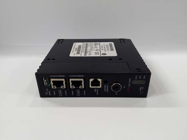
- Ethernet Ports: 2 x RJ-45 10/100 Mbps auto-sensing (redundant pair)
- Ethernet Protocols: SRTP, Modbus TCP, EGD
- Ethernet Redundancy: Automatic failover between primary and secondary ports
- Serial Ports: 2 x SNP/X (master/slave)
- Baud Rate: Up to 115.2 Kbaud
- Internal Coils (%M): 1024 bits per processor
- Timers/Counters: 340 combined per processor
- Scan Rate: 0.22 ms per 1K Boolean logic per processor (typical)
- Voting Circuit: 50-100 microseconds (processor synchronization and compare)
- Network Failover Time: < 100 ms (port-to-port switchover)
- Power Draw: 3.5 A @ +5 VDC (all three processors + dual Ethernet active)
- Operating Temperature: 0°C to 60°C (32°F to 140°F)
- SIL Rating: SIL 3 capable (per IEC 61508)

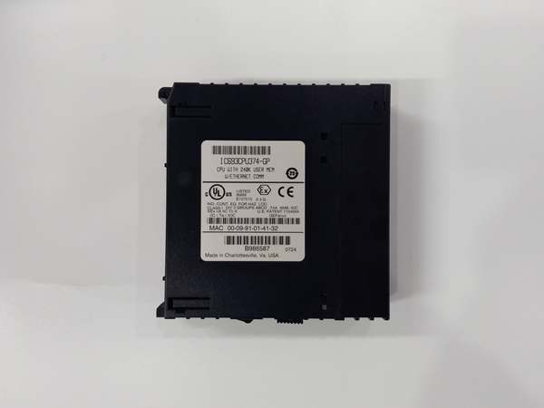
GE IC693CPU374
The Real-World Problem It Solves
Your TMR safety system has redundant CPUs and redundant power, but a single network switch failure takes down your entire safety system because you only have one Ethernet port. When that switch dies or someone trips over a cable, your safety system goes offline and your process trips to safe state unnecessarily. This CPU gives you two independent Ethernet ports with automatic failover—if the primary network fails, traffic switches to the secondary in under 100ms without losing communication or process continuity. Your safety system stays connected even when network components fail.
Where you’ll typically find it:
- Offshore Platform ESD Systems: Oil and gas platforms where network redundancy is critical due to harsh environment and limited physical routing options—single cable failure cannot compromise safety system connectivity
- Nuclear Power Plant Safety Systems: Facilities requiring maximum network redundancy where both safety and regulatory requirements mandate dual independent communication paths
- Critical Infrastructure Control: Power generation, water treatment, and chemical plants where safety system communication must survive single-point network failures to maintain continuous operation
Bottom line: It’s the CPU372 with redundant Ethernet—same 240K TMR architecture and SIL 3 capability, but with dual independent network ports that keep your safety system connected when the primary network fails.
Hardware Architecture & Under-the-Hood Logic
The IC693CPU374 extends the CPU372 architecture with dual independent Ethernet ports. Each of the three 80486DX4 processors has 240KB program and register memory, and the voting circuit operates identically to the CPU372. The key difference is the dual Ethernet hardware—two independent 10/100 Mbps controllers, each with its own MAC address and physical interface. The CPU presents a single IP address to the network, but internally, both Ethernet controllers can be connected to separate switches. A hardware failover circuit monitors link status on the primary port and switches traffic to the secondary port within 100ms if the primary fails.
-
Power-up and Network Initialization: All three processors boot simultaneously and load identical 240K programs. The dual Ethernet controllers initialize independently—the primary port (Port A) establishes link to Switch A, the secondary port (Port B) establishes link to Switch B. Both ports listen to the same IP address, but only the primary port transmits data under normal operation.
-
Normal Operation with Dual Networks: Under normal conditions, Port A (primary) handles all outbound and inbound traffic. Port B (secondary) maintains link to Switch B but does not transmit data. All three processors send identical data through the TMR voting circuit, which routes data to Port A for transmission. Incoming traffic arrives via Port A and is distributed to all three processors.
-
Automatic Network Failover: The hardware failover circuit continuously monitors link status on Port A using carrier sense and heartbeat detection. If Port A loses link (cable cut, switch failure, power loss), the failover circuit switches traffic to Port B within 100ms. Port B becomes active, takes over the IP address, and resumes communication. The TMR voting circuit redirects data to Port B automatically.
-
Transparent Switchover: The network failover is transparent to external devices—the IP address remains the same, no reconnection is required, and data continues flowing with minimal interruption. Connected devices (HMIs, SCADA, historians) see a brief pause (< 100ms) in communication, then normal traffic resumes.
-
TMR Coordination with Dual Ethernet: The voting circuit ensures all three processors send identical data, and only one coherent data stream reaches the active Ethernet port. During failover, the voting circuit redirects the data stream from Port A to Port B. All three processors maintain synchronization throughout—network failover does not affect TMR voting or processor synchronization.
-
Manual Network Selection: The CPU374 supports manual port selection via configuration. Operators can force traffic to use Port B instead of Port A for maintenance or testing purposes. Manual override is useful when upgrading network equipment or troubleshooting switch issues without causing automatic failover.
-
Dual Network Topology Options: The two Ethernet ports can be configured in several topologies:
- Dual Switch Redundancy: Port A to Switch A, Port B to Switch B (separate physical networks)
- Single Switch Dual Port: Both ports to the same switch (different VLANs for redundancy within one switch)
- Ring Topology: Ports connected to different points in a ring network for path redundancyThe selected topology depends on plant network architecture and redundancy requirements.
-
Power Draw with Dual Ethernet: Dual Ethernet controllers increase power draw to 3.5A @ +5VDC—higher than the 3.2A of the CPU372 with single Ethernet. Both Ethernet controllers are always powered and maintain link, even when only one is actively transmitting data. Calculate total current including all modules when designing power supply requirements.
-
Status Indication: The front panel includes separate LED indicators for Port A and Port B Ethernet status. LEDs show link status, activity, and failover state. Operators can visually identify which port is active and which is standby. Diagnostic software provides detailed network status including failover history, port health, and error counters.
-
Integration with TMR Diagnostics: Network failover events are logged in TMR diagnostic buffers. Operators can review failover history to identify chronic network issues. The voting circuit flags network faults without affecting CPU operation—network redundancy ensures the safety system continues functioning even if one Ethernet port fails completely.
GE IC693CPU374
Field Service Pitfalls: What Rookies Get Wrong
Connecting both ports to the same switch without VLAN separation
You plug both Ethernet cables into the same switch, no VLANs configured. The switch sees duplicate MAC addresses and flaps between ports, causing intermittent communication and network storms. Your safety system connectivity becomes unreliable.
Field Rule: If connecting both ports to the same physical switch, configure separate VLANs for Port A and Port B. This prevents MAC address conflicts and ensures proper failover behavior. Use switch port security and spanning tree protocol to prevent loops. Better yet, connect to separate physical switches for true network redundancy. Same-switch configuration is acceptable only with proper VLAN segmentation.
Assuming both ports transmit simultaneously
You configure both ports as active simultaneously to “double bandwidth.” This breaks IP addressing and causes communication failures. The CPU374 supports active-standby operation only—one port active, one standby. Dual active transmission is not supported and will cause network problems.
Field Rule: CPU374 Ethernet operates in active-standby mode only. One port (typically Port A) is active and handles all traffic. The other port is standby and takes over only when the active port fails. Do not attempt to configure dual active transmission. Design your network for failover redundancy, not load balancing. If you need bandwidth aggregation, use a managed switch with LACP instead of expecting the CPU to provide it.
Neglecting to configure both ports in programming software
You install the CPU374 but only configure IP settings for Port A. Port B remains unconfigured with default settings. When failover occurs, Port B attempts to use incorrect IP parameters and communication fails. Your redundancy is worthless because the standby port isn’t properly configured.
Field Rule: Configure both Ethernet ports in programming software, even though only one is active at a time. Set identical IP address, subnet mask, gateway, and DNS on both ports. Verify configuration on both ports before commissioning. Test failover by disconnecting Port A and confirming Port B assumes the IP address correctly. Unconfigured standby port means no redundancy.
Overlooking power supply capacity with dual Ethernet
You upgrade from CPU372 (3.2A) to CPU374 (3.5A) in an existing rack. The power supply is already loaded near capacity, and the extra 0.3A pushes it over the limit. The rack faults randomly under heavy network load because you exceeded power capacity.
Field Rule: CPU374 draws 3.5A minimum at +5VDC due to dual Ethernet controllers. Recalculate total rack current including all modules before upgrading. Derate for ambient temperature above 40°C. If your power supply is already near capacity, upgrade to a higher capacity supply or add a second supply. Don’t assume same CPU family means same power draw—dual Ethernet adds current load. Overloaded power supply will cause intermittent faults that are hard to diagnose.
Forgetting to test failover after commissioning
You commission the CPU374 with dual networks, verify communication works, and move on. Six months later, a switch fails and Port B doesn’t take over because it was never tested. You discover the secondary cable was bad all along when it’s too late.
Field Rule: Test network failover during commissioning. Disconnect Port A cable and verify Port B takes over within 100ms. Reconnect Port A and verify it resumes primary operation. Test failover in both directions (A to B and B to A). Document failover performance. Test periodically during maintenance to ensure redundancy still works. Untested redundancy is no redundancy at all—verify it actually works before you need it.
Misinterpreting failover alarms
You see a “Port A Failover” alarm and assume the CPU374 has failed. You replace the CPU unnecessarily. The real problem was a bad cable or switch failure—the CPU374 did its job by failing over to Port B.
Field Rule: Distinguish between CPU faults and network faults. “Port A Failover” indicates the primary network failed, not the CPU. The CPU374 switched to Port B as designed. Troubleshoot the network (cable, switch, switch port) before replacing the CPU. Check front panel LEDs—Port A LED off, Port B LED active confirms network failover. Don’t replace working hardware because the network failed. The CPU is doing its job—fix the network.
Mixing CPU372 and CPU374 in TMR set
You replace one failed CPU374 with a CPU372 because that’s what you have in spares. Both have 240K memory, so you think they’re compatible. The TMR system faults because CPU374 has dual Ethernet controllers and CPU372 has single Ethernet—they cannot synchronize network operations.
Field Rule: Never mix CPU models in a TMR set. CPU372 and CPU374 are not interchangeable despite identical memory capacity. CPU374 has dual Ethernet hardware that CPU372 lacks. All three processors must be identical models—all CPU372 or all CPU374. Maintain separate spares inventories for each model. If upgrading from CPU372 to CPU374, replace all three modules simultaneously during a planned outage.
Ignoring cable length limits with dual networks
You install redundant networks but use 150m Ethernet cables to reach both switches. This exceeds the 100m Ethernet limit, causing intermittent connectivity and failover issues. Your redundancy is compromised because both cables are borderline.
Field Rule: Ethernet cable length is limited to 100 meters (328 feet) per segment, regardless of redundancy. Both Port A and Port B cables must be within this limit. Use fiber media converters for distances exceeding 100m. Test cable integrity with a cable tester—verify signal strength, attenuation, and crosstalk on both cables. Redundant networks with bad cables are no better than single network with bad cables. Ensure both network paths meet installation standards.
Commercial Availability & Pricing Note
Please note: The listed price is for reference only and is not binding. Final pricing and terms are subject to negotiation based on current market conditions and availability.


