
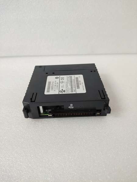
Description
System Architecture & Operational Principle
The IC693CPU374-DJ operates at Level 1 (Basic Control) of the ISA-95/Purdue Model. It resides in the main baseplate (often a 5 or 10-slot rack) and communicates with I/O modules via a parallel VME-style backplane (the “Rack Bus”). The CPU scans inputs from remote I/O blocks (Genius, VersaMax, or local 90-30 modules), executes the ladder logic or state machine program stored in non-volatile memory, and writes outputs back to the backplane. It acts as the traffic controller for the entire automation cell.
In terms of data flow, this CPU receives discrete and analog signals upstream from field devices (sensors, switches) via input modules. Downstream, it sends control commands to VFDs, valve actuators, and motor starters via output modules. Its inherent advantage lies in the 90-30 architecture: deterministic scan times and the ability to hot-swap many I/O modules without powering down the rack (with proper configuration), which is critical for continuous processes.
Power Budget Warning: The DJ revision draws significantly more current from the 5VDC rail than older 331/341 CPUs. On a fully populated baseplate, you must calculate the total 5V load. If you exceed the backplane power budget, the rack will brown out during peak scan or startup, causing phantom faults that look like hardware failure but are actually power starvation.
GE IC693CPU374
Core Technical Specifications
- CPU Speed: 0.3 ms/K (for typical Boolean logic)
- User Memory: 240 KB (Battery-backed RAM or Flash)
- Register Memory: 1024 words (%R)
- Discrete I/O Capacity: Up to 4096 points (mix of inputs/outputs)
- Analog I/O Capacity: Up to 128K words (via analog I/O modules)
- Communication Ports:
- Port 1: Serial RS-485 (SNP/SNPX Slave, Modbus RTU Master/Slave)
- Port 2: Serial RS-232 (Programmer Port – Logicmaster/Proficy Machine Edition)
- Programming Software: Proficy Machine Edition (PME) Logic Developer PLC
- Power Supply Requirements: 5VDC @ 1.2 Amps (from rack backplane); 24VDC for user transceiver power (Port 1 RS-485)
- Operating Temperature: 0°C to 60°C (32°F to 140°F)
- Relay/Transient Protection: Built-in ESD/RFI shielding on serial ports, but external surge protection is recommended for field wiring.
- Environmental: 5-95% relative humidity (non-condensing)
- Rack Compatibility: 90-30 CPU baseplates (IC693CHS39x series, IC693CHS777)
- Battery Type: 3.6V Lithium Thionyl Chloride (IC693ACC301 or equivalent)
Customer Value & Operational Benefits
Deterministic Control for Fast ProcessesThe 90-30 CPU374 provides consistent, repeatable scan times which is crucial for high-speed applications like packaging lines or parts handling. Unlike some modern PACs that prioritize communication flexibility over raw scan speed, the 374 delivers predictable performance every cycle. This means you can time your motion profiles with microsecond precision, reducing the need for complex timer compensations.
Proven Reliability & Extended SourcingThe “-DJ” revision is a mature design. It has been in the field for decades. The value here is that these units are readily available in the secondary market, meaning you can extend the life of an aging 90-30 system without a complete rip-and-replace. Replacing the CPU374 is a cost-effective strategy compared to migrating to a new PAC platform (like PACSystems RX3i), which would require new I/O modules, rewiring, and re-verification of safety logic.
Seamless Integration with Legacy PeripheralsThe DJ retains the dual serial ports (RS-232 & RS-485), which is a major operational benefit in brownfield sites. It can simultaneously talk to a legacy HMI via Modbus RTU on Port 2 and act as a gateway to a SCADA system on Port 1, or connect to a VFD using the built-in serial comms. This eliminates the need for external protocol converters, reducing potential failure points in the network architecture.
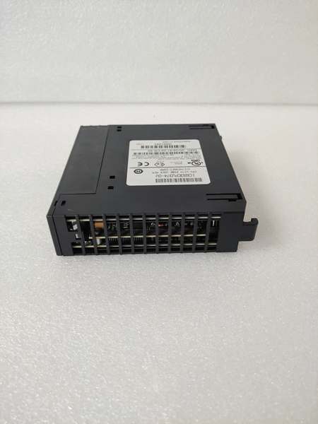
GE IC693CPU374
Field Engineer’s Notes (From the Trenches)
The “Phantom Fault” on the RS-485 Port: If you see intermittent communication loss on Port 1 (RS-485) only during thunderstorms or heavy switching, check your biasing and termination. The 374-DJ does not have internal 120-ohm termination resistors. You must add an external 120-ohm resistor across the Data+ and Data- lines at the farthest node. More importantly, if your cabling runs parallel to VFD output cables for more than 10 feet, you’re going to get noise coupling. I’ve seen this fry the transceiver chip on the CPU over time. The fix is simple: use shielded twisted pair with the drain wire grounded at ONE end only (typically the CPU rack ground), and add an opto-isolated RS-485 repeater if the run exceeds 3000 feet or if you’re in a high-noise environment.
Firmware Compatibility Trap: Never drop a “-DJ” CPU into a rack that was previously running a “-DS” or older firmware revision without checking the “Hardware Compatibility” setting in Machine Edition. Sometimes, older analog modules (like the ALG220) had specific handshaking requirements that changed with later CPU firmware. If you don’t update the hardware configuration to match the actual CPU revision, you’ll get a “Major Fault” on power-up. The fix isn’t to swap the CPU back; it’s to clear the memory, reconfigure the hardware setup for the -DJ revision, and redownload the logic.
Battery Warning: When the battery dies on a 374, the CPU goes to HALT state. Unlike the newer PACSystems CPUs that retain logic in Flash, the 90-30 relies on that battery to keep the RAM alive. If you have a machine that sits idle for months, that battery will be dead when you finally need to start up. Always keep a pre-tagged spare battery (IC693ACC301) in the cabinet. Replace it while power is ON to preserve the program and data.
Real-World Applications
- Hydrocracker Interlock Logic in an SIS Layer: In a refinery, the IC693CPU374-DJ can be used as the logic solver for non-critical interlocks (e.g., pump run-permissives, valve position verification) that feed into a certified Safety Instrumented System (SIS) like a Triconex controller. In this scenario, the 90-30 CPU collects status from hundreds of discrete sensors and performs complex permissive logic via Modbus RTU to the SIS. Its role is to reduce the nuisance trips on the SIS by filtering out transient signals and only sending a verified “Trip Request” when conditions persist beyond a defined time delay.
- Water Treatment Plant Flow Control & Pump Sequencing: In a municipal water treatment facility, the CPU374-DJ manages the operation of multiple variable frequency drives (VFDs) that control pumps maintaining constant pressure in the distribution network. The CPU reads 4-20mA flowmeters and pressure transmitters via analog input modules, executes a PID control loop, and sends speed reference commands to the VFDs via its serial port using a proprietary protocol (or Modbus). It also handles pump alternation logic to equalize wear and tear across the pump fleet, logging run hours that are pulled via SCADA for preventive maintenance scheduling.
High-Frequency Troubleshooting FAQ
Q: Can I swap an IC693CPU374-DJ directly with an IC693CPU374-DS in the field without reprogramming?A: No, not directly. While the form factor is identical, the internal firmware and memory addressing may differ between revisions. You must connect to the new -DJ CPU using Proficy Machine Edition, verify the Hardware Configuration matches the physical rack contents, and download the logic. Additionally, you will lose all data in the %R and %L registers (retentive memory) unless you perform an “Upload” from the old CPU and a “Download with Preserve” to the new CPU if the firmware versions are compatible. Always check the release notes for the specific firmware versions involved.
Q: How do I configure the DIP switches on the IC693CPU374-DJ?A: The CPU374-DJ has a bank of DIP switches (usually SW1) that control the default communication mode for Port 1 (RS-485). To set it up for Modbus RTU Slave: Switch 1 OFF, Switch 2 OFF, Switch 3 ON, Switch 4 OFF. For SNP Slave (legacy GE): Switch 1 OFF, Switch 2 ON, Switch 3 OFF, Switch 4 ON. Crucial Step: After setting the physical DIP switches, you MUST power-cycle the CPU for the changes to take effect. If you don’t cycle power, the serial port will remain in the previous mode, and your Modbus master will get a timeout. Also, ensure the baud rate switch settings match your master device exactly.
Q: What does a solid red “OK” LED (or fault LED pattern) on the CPU374-DJ indicate?A: On the 90-30 CPU, a flashing red “RUN/OK” LED typically indicates a recoverable error or that the CPU is in HALT/Stop mode. A solid red (if present) or the “FAULT” LED being lit usually points to a hardware or major configuration fault. Common causes include: 1) Missing or corrupt logic – the CPU powered up with empty memory; 2) I/O Module Mismatch – the configured hardware in PME doesn’t match the actual modules in the rack; 3) Watchdog Timer Fault – the scan time exceeded the configured watchdog limit (e.g., the program became too complex or got stuck in an endless loop). The first step is to connect via Port 2 (RS-232) and read the Fault Table in Machine Edition to get the specific fault code.
Q: My IC693CPU374-DJ keeps losing the program when power is cycled. Is the CPU bad?A: Not necessarily. The 90-30 stores the user program in volatile RAM backed by the lithium battery. If the program vanishes on power cycle, check the battery voltage first. If the battery is dead or missing, the RAM clears immediately upon power loss. However, if the battery is good (3V+), the issue might be the Memory Protect switch (usually located near the battery or on a different module). Ensure the memory protect is OFF to allow writes. If both are fine, and the program still disappears, the RAM chip on the CPU could be failing, which means the CPU needs replacement or repair.
Please note: The listed price is not the actual final price. It is for reference only and is subject to appropriate negotiation based on current market conditions, quantity, and availability.


