
Description
Hard-Numbers: Technical Specifications
- Processor: Three (3) x Intel 80486DX4, 25 MHz clock per processor
- Architecture: Triple Modular Redundancy (TMR) – 3-vote 2-out-of-3
- User Program Memory: 80 KB per processor (240 KB total)
- Register Memory: 240 KB per processor (720 KB total)
- Floating Point: Supported (32-bit hardware per processor)
- Discrete I/O: 2048 points max combined (%I + %Q) with TMR support
- Analog Input (%AI): 128 words (up to 8K with option modules) per processor
- Analog Output (%AQ): 64 words (up to 8K with option modules) per processor
- Internal Coils (%M): 1024 bits per processor
- Discrete Global Memory (%G): 1280 bits per processor
- Timers/Counters: 340 combined per processor
- Scan Rate: 0.22 ms per 1K Boolean logic per processor (typical)
- Voting Cycle: 50-100 microseconds (processor synchronization and compare)
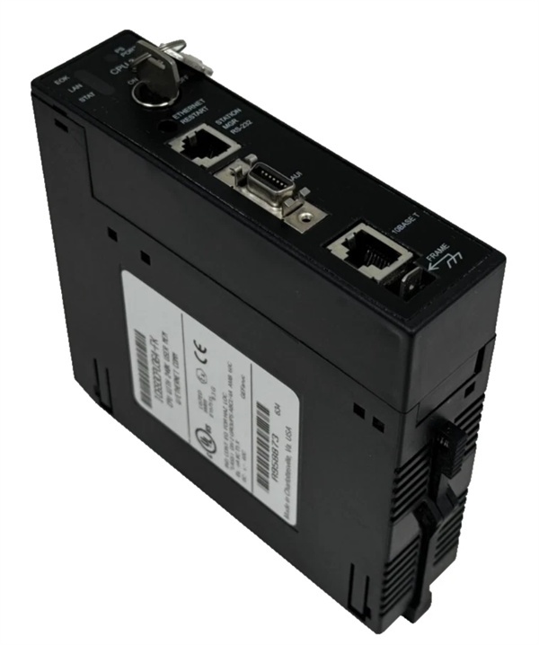
- Serial Ports: 2 (Port 1: SNP/X master/slave, Port 2: SNP/X master/slave)
- Baud Rate: Up to 115.2 Kbaud
- Ethernet Port: 1 x RJ-45 10/100 Mbps auto-sensing (TMR-aware)
- Ethernet Protocols: SRTP, Modbus TCP, EGD (TMR-coordinated)
- Expansion: Yes (up to 7 baseplates including remote) with TMR support
- Battery-Backed Clock: Yes (per processor, synchronized)
- Power Draw: 3.2 A @ +5 VDC (all three processors active)
- Operating Temp: 0°C to 60°C (32°F to 140°F)
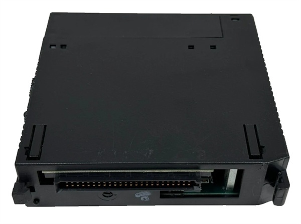
- Module Type: Modular (plugs into CPU slot)
- SIL Rating: SIL 3 capable (per IEC 61508) with proper system design
- Fault Detection: Automatic single-processor failover without process interruption

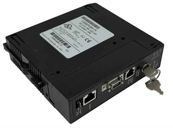
GE IC693CPU364
The Real-World Problem It Solves
Your safety-critical process can’t tolerate a single-point CPU failure. If one processor locks up, the plant keeps running safely or shuts down gracefully without a spurious trip. This TMR CPU runs three independent processors in lockstep, comparing every output and voting 2-out-of-3. If one disagrees, the majority rules and the bad processor is flagged without disrupting the process.
Where you’ll typically find it:
- Emergency Shutdown (ESD) Systems: Offshore platforms, refineries, petrochemical plants where single CPU failure causing a spurious shutdown would cost millions in lost production and safety incidents
- Fire & Gas Detection Systems: Critical facilities requiring continuous operation even during CPU faults—nuclear plants, chemical reactors, power generation
- Turbine Generator Control: Critical power generation equipment where CPU failure must not cause turbine trips or load rejection
Bottom line: It’s the ultimate in Series 90-30 CPU redundancy—three processors voting every output, automatic failover without process interruption, and SIL 3 capability for safety-critical applications where downtime is unacceptable.
Hardware Architecture & Under-the-Hood Logic
The IC693CPU364 contains three independent Intel 80486DX4 processors running identical programs in lockstep. Each processor has its own memory (80K program, 240K registers) and executes the same ladder logic simultaneously. A dedicated TMR compare circuit continuously votes processor outputs and selects the 2-out-of-3 majority result. The CPU outputs the voted result to backplane—I/O and communication modules see a single, fault-tolerant output.
-
Power-up sequence initializes all three 80486DX4 processors simultaneously. Each processor runs independent diagnostics and loads identical configuration from NVRAM. The TMR compare circuit synchronizes the three processors within 50-100 microseconds—voting cycle begins once all three report ready status. Battery-backed clocks initialize per processor and are synchronized by the compare circuit.
-
TMR voting mechanism operates on a continuous 50-100 microsecond cycle. All three processors calculate outputs independently and present them to the compare circuit. The compare circuit votes on every discrete output, every register write, and every analog value. 2-out-of-3 majority becomes the CPU output. If one processor disagrees, it’s flagged as faulty and its outputs are ignored—the other two continue providing correct voted outputs.
-
Single-processor failure is detected and handled automatically. If Processor A disagrees with Processors B and C, the compare circuit flags Processor A as faulty and ignores its outputs. The CPU continues operating with Processors B and C (2-vote operation remaining). No process interruption occurs—outputs remain correct based on B and C agreement. Operators are notified of Processor A fault but the process continues safely.
-
Dual-processor failure triggers safe state. If Processors B and C also disagree or fail, the compare circuit can no longer maintain a 2-out-of-3 majority. The CPU outputs freeze in last known good state or go to predefined safe state per configuration. I/O outputs can be configured to fail-safe (e.g., shutdown valves open/close based on safety requirements). The process enters a safe state—either continues in degraded mode or shuts down per safety logic.
-
Ethernet operation in TMR mode requires special consideration. The integrated Ethernet port presents a single IP address to the network despite three internal processors. Network traffic is coordinated by the TMR compare circuit—all three processors send identical data, and the compare circuit ensures only one data stream reaches the network. Modbus TCP, SRTP, and EGD operate seamlessly from the network perspective—external devices see a single, reliable PLC IP address.
-
Backplane communication with TMR I/O modules (IC693TMRxxx series) provides complete fault tolerance. Standard I/O modules work with TMR CPU but don’t provide module-level redundancy. For full safety-critical systems, use TMR-specific I/O modules that perform input voting and output drive per processor. Standard I/O modules receive the voted output from the CPU—if the CPU fails to 2-vote mode, standard I/O continues operating with the remaining processors.
-
Serial ports operate identically to standard CPUs (Port 1 and Port 2, SNP/X master/slave). Serial communication doesn’t benefit from TMR architecture—a single serial port per CPU. If serial communication is safety-critical, design redundancy by using both serial ports to separate master devices or using Ethernet as primary communication with serial as backup.
-
Memory architecture per processor is identical to standard 360. Each processor has 80K program memory and 240K register memory. Programs are identical across all three processors—loaded once and replicated by the TMR system. Register synchronization occurs continuously via the compare circuit—register writes from any processor are voted and replicated to all processors. Consistency is guaranteed across the TMR system.
-
Scan rate per processor is 0.22 ms per 1K Boolean logic (identical to CPU360). However, the voting cycle adds 50-100 microseconds of overhead to every scan. Effective scan time including voting is approximately 0.25-0.3 ms per 1K logic. This remains fast enough for virtually all industrial control applications. The TMR overhead is minimal compared to the safety benefit.
-
Power consumption is 3.2 A at +5 VDC—all three processors active simultaneously. This is double the current draw of a single-processor CPU (1.6A for CPU360). IC693PWR330 (5A @ +5VDC) is the minimum recommended power supply. For heavily loaded racks, consider adding a second power supply in the CPU rack or moving high-current modules to expansion racks with their own supplies. Never exceed power supply rating—a brownout in a TMR system defeats the redundancy benefit.
-
SIL 3 capability requires proper system design beyond just the TMR CPU. Per IEC 61508, the overall safety system—including I/O modules, power supplies, sensors, and final elements—must be designed to meet SIL 3 requirements. The CPU364 provides the processor redundancy portion of a SIL 3 system. Use TMR I/O modules, redundant power supplies, and properly designed safety logic to achieve full SIL 3 certification for the application.

GE IC693CPU364
Field Service Pitfalls: What Rookies Get Wrong
Assuming TMR prevents all faults
You install a CPU364 and think it’s bulletproof. A power supply fails and your TMR system goes down anyway. TMR protects against CPU failures—not power supply failures, I/O module failures, or wiring faults.
- Field Rule: TMR only protects the CPU. For full redundancy, you need redundant power supplies, TMR I/O modules, redundant sensors, and redundant final elements. A single power supply failure kills all three processors simultaneously. Design your safety system holistically—CPU redundancy is one component. Don’t assume TMR makes the entire system fault-tolerant.
Ignoring TMR I/O requirements
You use standard I/O modules with a TMR CPU. An I/O module fails and causes a spurious trip. The CPU kept running but the I/O failed—TMR didn’t help.
- Field Rule: TMR CPUs require TMR I/O modules for full safety-critical protection. Standard I/O modules work but provide single-point failure points. For SIL 3 applications, use IC693TMRxxx series I/O modules that perform input voting (3 inputs voted to 1) and output drive per processor. TMR I/O plus TMR CPU creates a fault-tolerant path from field to logic to output. Don’t cheap out on I/O—it defeats the purpose of TMR.
Misinterpreting fault alarms
You see a “Processor A Fault” alarm and shut down the process immediately. The CPU was running perfectly fine in 2-vote mode—you caused an unnecessary shutdown.
- Field Rule: Single-processor faults are not process emergencies. The TMR system continues operating with two processors in 2-out-of-3 voting. Single-processor faults are maintenance notifications, not shutdown triggers. Schedule processor replacement at the next planned outage. Continue operating the process—redundancy is working as designed. Only shut down for dual-processor faults or system-level alarms.
Hot-swapping failed processors
You pull a failed CPU364 to replace Processor A without powering down. You corrupt the TMR configuration and possibly damage the replacement CPU.
- Field Rule: NEVER hot-swap TMR CPUs. Power down the entire rack before removing or installing any TMR CPU. The compare circuit and synchronization logic can be corrupted by hot insertion/removal. TMR systems are designed to survive processor failures, not hot swaps. Schedule processor replacement during planned outages. If you need hot-swap capability, design a dual-rack TMR system with transfer switching.
Neglecting to replace failed processors promptly
A failed Processor A has been flagged for six months. Processor B fails, and now the system goes to safe state because only Processor C remains. You had time to fix A but didn’t.
- Field Rule: Replace failed processors promptly. Operating in 2-vote mode is safe but provides no further redundancy—if a second processor fails, you’re down. Schedule processor replacement at the next available outage. Maintain spare TMR CPUs in inventory. Don’t let the system operate with a degraded processor for extended periods—tempting fate.
Underestimating power supply requirements
You install a CPU364 into a rack with IC693PWR321. The rack won’t power up or faults randomly. 3.2A for the CPU plus module draw exceeds the 321’s capacity.
- Field Rule: Do the math before powering up. IC693CPU364 = 3.2A @ +5VDC minimum. Add every module’s current draw. For any TMR application, use IC693PWR330 (5A @ +5VDC) as absolute minimum. Consider dual power supplies for critical applications. Never exceed power supply rating—a brownout defeats TMR by killing all processors simultaneously. Calculate carefully, especially in high-temperature environments.
Confusing TMR with hot standby
You think the TMR system has a standby processor waiting to take over. All three processors are active simultaneously—there’s no “standby” processor.
- Field Rule: TMR is 3-vote 2-out-of-3, not hot standby. All three processors execute the same program continuously. Voting occurs every cycle—no switchover delay. Hot standby systems have a standby processor that takes over when the primary fails with some delay. TMR provides zero-latency failover because all processors are always active. Understand the difference—TMR is active-active, not active-standby.
Overlooking Ethernet configuration in TMR mode
You configure IP address on Processor A and expect Processors B and C to inherit it. Network communication fails because B and C have default IPs.
- Field Rule: TMR configuration requires all three processors to have identical network settings. When configuring Ethernet, ensure IP address, subnet mask, gateway, and DNS are identical across all processors. The TMR compare circuit ensures only one data stream reaches the network, but all processors must have consistent configuration. Configure once and verify settings propagated to all three processors in programming software. Mismatched network config causes communication failures.
Forgetting that TMR scan time includes voting overhead
You migrate from CPU360 to CPU364 and expect identical scan time. Scan time increases by 0.05-0.08 ms per 1K logic due to voting cycle.
- Field Rule: TMR adds voting overhead to scan time. The 50-100 microsecond voting cycle adds to the base 0.22 ms/K scan rate. Effective scan time is approximately 0.25-0.3 ms/K. For most applications, this increase is negligible. However, if your logic was pushing the watchdog limit on a CPU360, the TMR overhead could push you over. Recalculate scan time after migrating to TMR and adjust watchdog timers if necessary.
Assuming SIL 3 is automatic
You install a CPU364 and claim SIL 3 compliance. A safety auditor rejects your certification because the overall system wasn’t designed to SIL 3.
- Field Rule: SIL 3 requires system-level design, not just a TMR CPU. Per IEC 61508, the entire safety function—from sensors to logic to final elements—must meet SIL 3 requirements. The CPU364 provides processor redundancy, but you also need redundant sensors, TMR I/O modules, redundant power supplies, properly diagnosed failure modes, and validated safety logic. SIL certification is a process, not a product purchase. Don’t market a TMR CPU as SIL 3 without proper system design and validation.
Ignoring TMR diagnostic capabilities
You troubleshoot a TMR CPU using standard CPU364 documentation. You miss TMR-specific diagnostics that would pinpoint which processor is faulty and why.
- Field Rule: TMR CPUs provide enhanced diagnostics beyond standard CPUs. Use programming software with TMR diagnostic support—VersaPro and Proficy display individual processor status, voting statistics, and fault details. Monitor TMR alarms regularly: processor disagreements, sync errors, compare circuit faults. TMR diagnostics tell you exactly which processor failed and why—use them. Don’t treat a TMR CPU like a standard CPU during troubleshooting.
Commercial Availability & Pricing Note
Please note: The listed price is for reference only and is not binding. Final pricing and terms are subject to negotiation based on current market conditions and availability.


