
Description
Hard-Numbers: Technical Specifications
- Processor: Intel 80486DX4, 25 MHz clock
- User Program Memory: 80 KB
- Register Memory: 240 KB (%R addressing)
- Floating Point: Supported (32-bit hardware)
- Discrete I/O: 2048 points max combined (%I + %Q)
- Analog Input (%AI): 128 words (up to 8K with option modules)
- Analog Output (%AQ): 64 words (up to 8K with option modules)
- Internal Coils (%M): 1024 bits
- Discrete Global Memory (%G): 1280 bits
- Timers/Counters: 340 combined
- Scan Rate: 0.22 ms per 1K Boolean logic (typical)
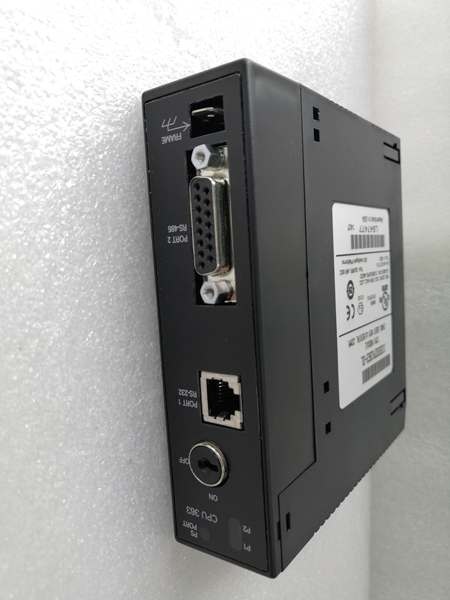
- Serial Ports: 2 (Port 1: SNP/X master/slave, Port 2: SNP/X master/slave)
- Baud Rate: Up to 115.2 Kbaud
- Ethernet Port: 1 x RJ-45 10/100 Mbps auto-sensing
- Ethernet Protocols: SRTP, Modbus TCP (Master/Slave), Ethernet Global Data (EGD)
- Max Server Connections: Up to 16 simultaneous TCP/IP connections
- Expansion: Yes (up to 7 baseplates including remote)
- Battery-Backed Clock: Yes (on-board CR2032)
- Power Draw: 1.8 A @ +5 VDC (higher than 360 due to Ethernet)
- Operating Temp: 0°C to 60°C (32°F to 140°F)
- Storage Temp: -40°C to 85°C (-40°F to 185°F)
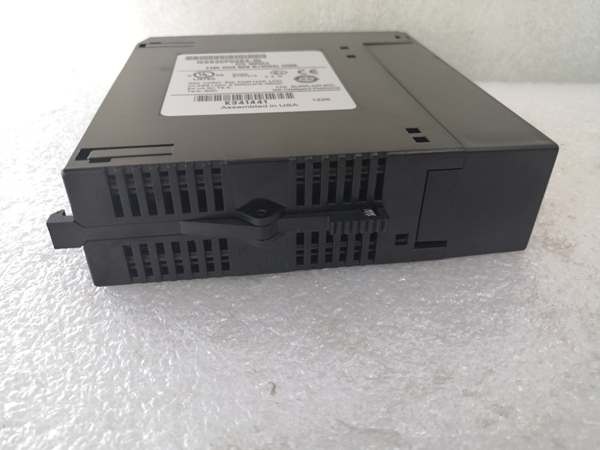
- Module Type: Modular (plugs into CPU slot)
- Interrupts: Supported (up to 32)
- Subroutines: Supported (up to 64)

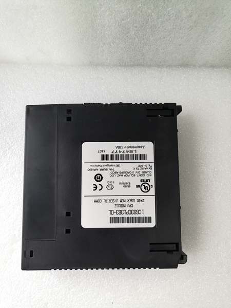
IC693CPU363
The Real-World Problem It Solves
You need Ethernet connectivity for SCADA, HMIs, or PLC-to-PLC communication, but you’re out of I/O slots and can’t afford to burn one on an Ethernet module like IC693CMM321. This CPU integrates TCP/IP Ethernet directly onto the board—RJ-45 port right on the CPU faceplate, no module required. You keep all your I/O slots available while getting high-speed networking built-in.
Where you’ll typically find it:
- SCADA-integrated process plants: Water treatment facilities, power plants, and chemical plants where Series 90-30 PLCs connect directly to Ethernet-based SCADA systems via Modbus TCP or SRTP
- Networked HMI systems: Manufacturing floors with multiple panel HMIs connecting over Ethernet to shared PLCs without consuming I/O slots for communication modules
- Multi-PLC EGD systems: Applications requiring cyclic data exchange between multiple Series 90-30 PLCs using Ethernet Global Data for coordinated motion and material tracking
Bottom line: It’s essentially a 360 CPU with built-in Ethernet—same performance, memory, and expansion capability, plus TCP/IP networking without sacrificing an I/O slot for an external Ethernet module.
Hardware Architecture & Under-the-Hood Logic
The IC693CPU363 maintains the standard 360 architecture (Intel 80486DX4, 80K program memory, 240K register memory) with the addition of an integrated 10/100 Mbps Ethernet controller on the CPU board. This controller connects to an RJ-45 port on the faceplate, eliminating the need for external Ethernet modules like IC693CMM321. The Ethernet interface operates independently of the main scan cycle.
-
Power-up sequence initializes the 80486DX4 core, memory diagnostics, and NVRAM configuration. Simultaneously, the integrated Ethernet controller initializes and attempts DHCP (if configured) or loads static IP address from NVRAM. Battery-backed clock initializes—low battery flags %S0012. Serial ports and backplane drivers come online after Ethernet initialization completes.
-
Integrated Ethernet controller operates through a dedicated TCP/IP stack in the CPU’s microcode. This stack handles IP addressing, TCP/UDP packet assembly, and protocol execution (SRTP, Modbus TCP, EGD) independently of ladder logic execution. The Ethernet portion of the CPU has its own processing resources separate from the main 80486DX4, though they share access to CPU memory (%R) for data exchange.
-
SRTP (Serial Real-Time Protocol over TCP/IP) allows GE Fanuc programming software and HMIs to communicate with the CPU over Ethernet. The CPU acts as both SRTP client and server. As a server, it listens for incoming connections (default port 18245) from programming software for online edits, monitoring, and program transfers. As a client, it can initiate SRTP connections to other GE Fanuc PLCs or HMIs using COMMREQ blocks in ladder logic.
-
Modbus TCP provides standard industrial protocol support. The CPU can function as Modbus TCP Master (client) or Slave (server). As a slave, it responds to Modbus TCP read/write requests from SCADA systems, third-party HMIs, or PLCs. As a master, it initiates Modbus TCP requests to slave devices using ladder logic COMMREQ blocks. Modbus mapping is configured in programming software—map PLC memory (%I, %Q, %R, %AI, %AQ) to Modbus holding/input/ coils and registers.
-
Ethernet Global Data (EGD) enables cyclic data exchange between multiple Series 90-30 PLCs. Configure EGD exchanges in programming software—define PLC memory blocks (%R) to transmit at configured intervals (10-1000 ms). The Ethernet controller handles cyclic transmission independently of the scan cycle. Up to 16 EGD exchanges can be configured per CPU. EGD typically uses UDP for low-latency cyclic communication.
-
RJ-45 port on the CPU faceplate provides standard Ethernet connection (auto-sensing 10/100 Mbps). No external transceiver or AAUI cable required—unlike IC693CMM321 which needs external transceiver. Connect standard Cat5/5e/6 cable directly to the CPU port. LED indicators on the faceplate show link status and network activity. Port auto-negotiates speed and duplex automatically.
-
Maximum 16 simultaneous TCP/IP connections can be maintained. This includes SRTP, Modbus TCP, and any other TCP-based protocols running concurrently. For example, you can have 4 SRTP programming connections, 8 Modbus TCP slaves, and 4 EGD exchanges operating simultaneously. Exceeding 16 connections results in connection rejection or dropped sessions.
-
Backplane communication and expansion rack operation remain identical to standard 360. The CPU scans Rack 0 through Rack 7, gathering I/O images from each rack. Ethernet operations occur asynchronously—the Ethernet controller accesses memory independently, though both compete for memory bandwidth. Heavy network traffic can slightly increase scan time due to memory bus contention, but the dedicated Ethernet controller minimizes impact.
-
Serial ports (Port 1 and Port 2) operate independently of Ethernet. Both support SNP/X master/slave up to 115.2 Kbaud. You can run serial communication simultaneously with Ethernet—no conflicts. Serial communication uses the same COMMREQ architecture as Ethernet master connections. Port 1 and Port 2 are unaffected by Ethernet operations—they remain available for legacy devices or backup communication paths.
-
Power consumption is 1.8 A at +5 VDC—higher than standard 360 (1.6A) due to integrated Ethernet controller. The Ethernet interface draws additional current, especially during high network traffic. IC693PWR330 (5A @ +5VDC) is recommended for most 363 applications. Calculate total current: CPU (1.8A) + all module currents. The higher power draw becomes critical in high-temperature environments—derate the power supply appropriately.

IC693CPU363
Field Service Pitfalls: What Rookies Get Wrong
Assuming the Ethernet port works like a standard PC NIC
You treat the RJ-45 port like any office PC network card. You connect it directly to an unmanaged switch with no configuration and expect everything to work. No IP address is set, DHCP fails, and communication doesn’t happen.
- Field Rule: The Ethernet port requires initial configuration before communication works. Use VersaPro or Proficy to configure IP address, subnet mask, gateway, and DNS settings. Static IP addressing is strongly recommended—DHCP support is limited and unreliable in industrial environments. Verify IP uniqueness on the network before deployment. Set static IPs outside the DHCP range to avoid conflicts. Configure the port before relying on it for production.
Confusing Modbus TCP mapping with discrete I/O addressing
You expect Modbus registers to automatically map to %I and %Q addresses. SCADA can’t read your process data because nothing is mapped.
- Field Rule: Modbus TCP requires explicit configuration. In programming software, map PLC memory to Modbus addresses:
- Modbus Coils (0x) map to %I and %Q
- Modbus Discrete Inputs (1x) map to %I
- Modbus Holding Registers (4x) map to %R and %AQ
- Modbus Input Registers (3x) map to %AI and %RVerify mapping after configuration. Modbus tools can test connectivity before SCADA integration. Don’t assume automatic mapping—configure it explicitly and test with a Modbus client utility.
Overloading the 16-connection limit
You connect 20 HMIs to the same CPU. Some HMIs randomly disconnect. You blame network switches when the CPU has hit its connection limit.
- Field Rule: Maximum 16 simultaneous TCP/IP connections. Count everything: SRTP programming connections, Modbus TCP masters, Modbus TCP slaves, EGD exchanges, HMI connections. If you need more, install a second Ethernet module (IC693CMM321) in an I/O slot—this provides additional connections up to 16 more. Monitor active connections in programming software. Plan connection allocation during system design—don’t discover the limit during commissioning.
Running Ethernet cables through conduit with power cables
You route the RJ-45 cable through the same conduit as 480V motor feeds. Network performance is erratic—dropouts, slow response, CRC errors. EMI kills TCP/IP packets.
- Field Rule: Keep Ethernet cables separate from power. Minimum 6 inches separation, preferably in separate conduit. Use shielded Cat5e/6 cable with properly grounded foil shield. Industrial Ethernet cable (IP67-rated connectors) is recommended for harsh environments. If you must cross power, do it at 90 degrees. Network performance in industrial environments demands proper cable management—don’t treat Ethernet like office networking.
Forgetting that Ethernet consumes I/O slots no more
You plan your rack layout assuming you’ll need an Ethernet module and reserve a slot. The CPU has built-in Ethernet—no module required. You’re wasting a perfectly good I/O slot.
- Field Rule: The 363’s Ethernet is integrated—no external module required. Use all 10 I/O slots (including Slot 1) for actual I/O. The Ethernet port is on the CPU faceplate itself. Don’t reserve slots for communication modules unless you need additional protocols (Profibus, DeviceNet) beyond TCP/IP. The RJ-45 is right there on the front—use it.
Neglecting to set up EGD timing correctly
You configure EGD exchanges between PLCs but data arrives late or out of sequence. Critical interlocks fail because timing is wrong.
- Field Rule: EGD exchange interval must match application timing requirements. Fast cyclic exchanges (10-50 ms) are needed for motion coordination; slower exchanges (500-1000 ms) work for general data sharing. Configure identical exchange intervals on both sides of the EGD connection. Mismatched timing causes data synchronization errors. Test EGD communication with known data values before trusting it in production. Monitor EGD statistics for lost packets or excessive retries.
Underestimating power supply requirements
You install a 363 into a rack with IC693PWR321 and multiple analog modules. The PLC faults randomly under load. The 363 draws 1.8A—the 321’s 3A rating leaves little headroom for anything else.
- Field Rule: Do the math before powering up. IC693CPU363 = 1.8A @ +5VDC minimum. Add every module’s current draw. For most 363 applications, use IC693PWR330 (5A @ +5VDC) as minimum. The Ethernet controller adds approximately 200 mA over the standard 360 base draw. Never exceed power supply rating—brownouts corrupt NVRAM and force full reload. Calculate carefully, especially in high-temperature environments where power supplies are derated.
Mixing CPU363 and CMM321 in the same system
You install a CPU363 and also add a CMM321 Ethernet module for “more ports.” You have two separate Ethernet stacks consuming memory and causing confusion.
- Field Rule: CPU363 has built-in Ethernet—you generally don’t need a separate CMM321 unless you require two physically separate networks (network segmentation) or additional protocol support beyond what the 363 provides. Two Ethernet stacks require independent IP configuration and consume more resources. Plan for segmentation or redundancy explicitly—don’t just throw in a second Ethernet module without a clear purpose. The 363’s built-in port is usually sufficient.
Forgetting that Ethernet communication requires COMMREQ blocks for client mode
You expect the CPU to automatically initiate Modbus TCP connections to other PLCs. Nothing happens because you didn’t write the COMMREQ blocks.
- Field Rule: Ethernet client mode (initiating connections) requires COMMREQ blocks in ladder logic, just like serial master mode. The CPU doesn’t automatically act as a client. Write COMMREQ blocks to open TCP connections, send Modbus TCP requests, and handle responses. Configure COMMREQ parameters: IP address, port number, function code, memory mapping. Test COMMREQ blocks with known target devices before production. Client mode is logic-driven—write the code.
Ignoring the faceplate Ethernet LED indicators
The LINK and ACT LEDs are dark, but you assume the cable is fine because it worked yesterday. You waste hours troubleshooting ladder logic when the physical link is down.
- Field Rule: Check the faceplate LEDs first. LINK LED = green steady when connected to a switch. ACT LED = green flashing when network traffic occurs. If LINK is dark, you have a physical layer problem: bad cable, unplugged port, switch down, or IP conflict. Fix physical layer before diving into software configuration. The LEDs tell you instantly if Ethernet is alive—use them as your first diagnostic step.
Failing to back up after IP changes
You change the IP address from static to DHCP and reboot. The PLC gets an IP you don’t know, and now you can’t connect to reconfigure. You’re locked out of your own PLC.
- Field Rule: Always back up configuration before making IP changes. If you switch to DHCP, note the assigned IP address immediately (from switch DHCP table or network scanner). If you can’t connect after IP change, connect via serial port (Port 1) to read the current IP configuration. Maintain a serial backup connection whenever making network changes—don’t paint yourself into a corner where Ethernet is your only access and it’s unreachable.
Commercial Availability & Pricing Note
Please note: The listed price is for reference only and is not binding. Final pricing and terms are subject to negotiation based on current market conditions and availability.


