
Description
Hard-Numbers: Technical Specifications
- Processor Type: Intel 80188 embedded processor
- Processor Speed: 10 MHz clock rate
- User Program Memory: 12 KB maximum (6 KB for firmware versions prior to release 7)
- Register Memory (%R): 2 KB (1024 words)
- Typical Scan Rate: 0.6 milliseconds per 1K of Boolean logic
- Discrete I/O Capacity: 320 points maximum (combined %I inputs and %Q outputs)
- Analog Input (%AI): 64 words
- Analog Output (%AQ): 32 words
- Internal Coils (%M): 1024 bits
- Discrete Global Memory (%G): 1280 bits
- Output/Temporary Coils (%T): 256 bits
- System Status References (%S): 128 bits (%S, %SA, %SB, %SC—32 bits each)
- Timers/Counters: 340 units combined
- Floating Point Math: Not supported
- System Architecture: 16-bit system
- Number of Slots: 10 slots (9 for I/O/option modules + 1 for power supply)
- Built-in Serial Ports: 1 (uses connector on PLC power supply)
- Supported Serial Protocols: SNP Slave and SNP-X Slave only
- Optional Communication Modules: Ethernet TCP/IP, FIP, Profibus, GBC, GCM, GCM+
- PCM/CCM Compatibility: No (not supported)
- Expansion Support: None—no expansion baseplate connector, no remote rack support
- Battery-Backed Clock: Not supported (battery located in power supply module)
- Program Interrupts: Not supported
- Override Function: Not supported
- Shift Registers: Supported
- Power Requirements: 5 VDC from power supply
- Current Draw: 430 mA from +5 VDC supply
- Operating Temperature: 0°C to 60°C (32°F to 140°F) ambient
- Storage Temperature: -40°C to 85°C (-40°F to 185°F)
- Dimensions: 263 mm × 58 mm × 28 mm (10.3 in × 2.3 in × 1.1 in)
- Weight: 2.07 lbs (0.94 kg)
- Humidity: 5% to 95% non-condensing
- Default Rack Number: Always assigned Rack Number Zero (0) by default
- Configuration Switches/Jumpers: None on baseplate

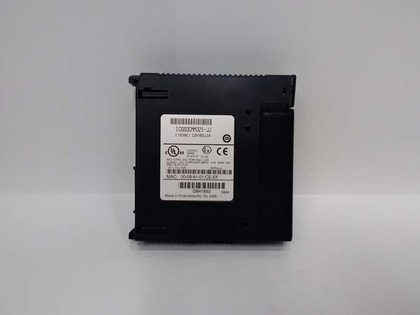
GE IC693CMM321
The Real-World Problem It Solves
You need a compact PLC for a standalone machine—conveyor control, small batch mixer, packaging system—where space is tight and budget matters. A full modular rack with separate CPU module is overkill. You want all 10 slots available for I/O modules, not wasted on a CPU module. The IC693CPU323 embeds the processor directly into the backplane, saving space and cost while delivering 0.6 ms/1K scan performance.
Where you’ll typically find it:
- Small Material Handling: Package sorters, conveyors, feeders, diverters—applications with 100-200 I/O points needing fast response
- Process Control: Small batch reactors, mixers, heat exchangers—PID loops with analog I/O and logic sequencing
- Packaging Lines: Labelers, fillers, sealers, cartoners—high-speed discrete control with sensor integration
- Single-Machine Automation: Standalone equipment requiring self-contained PLC control without expansion needs
- Building Automation: HVAC control, pump stations, lighting control—moderate I/O counts with network integration via optional modules
Bottom line: This is the economy choice for Series 90-30 systems—embedded CPU saves cost and space, delivers solid performance for small applications, but sacrifices expansion, advanced features, and upgrade flexibility.
Hardware Architecture & Under-the-Hood Logic
The IC693CPU323 integrates CPU and memory chips directly onto the backplane board. This embedded architecture reduces cost and component count but makes the CPU non-replaceable. The Intel 80188 processor executes ladder logic, handles I/O updates via the backplane bus, and manages serial communication through the power supply connector. No CPU module slot means all 10 numbered slots are available for I/O and option modules.
-
Power-Up and Initialization SequenceAt power-on, the backplane draws 5 VDC from the power supply module. The 80188 processor initializes internal registers and begins POST (Power-On Self-Test). System status references (%S, %SA, %SB, %SC) initialize to default states. The processor reads configuration data from battery-backed RAM if valid, or defaults to RUN mode if no program exists. Battery-backed RAM resides on the backplane board—retention depends on the power supply module’s battery. If power supply is unplugged, the backplane’s super capacitor provides approximately 1 hour of memory retention. Once initialized, the CPU enters configured mode (RUN, STOP, or disabled) and begins scanning ladder logic.
-
Processor and Memory ArchitectureThe Intel 80188 is a 16-bit microprocessor optimized for embedded control. At 10 MHz, it executes ladder logic instructions with deterministic timing. Memory allocation is fixed:
- User program storage: Up to 12 KB for ladder logic, subroutine blocks, and comment data
- Register memory (%R): 1024 words (2048 bytes) for data storage
- Discrete memory (%I, %Q, %M, %G, %T, %S): Bit-addressable locations mapped to I/O modules and internal coils
- Analog memory (%AI, %AQ): 64 input words and 32 output words for analog I/O modulesThe 80188 does not support floating-point math—all arithmetic is integer-based (16-bit signed operations). Floating-point values must be scaled to integers before processing.
-
Scan Cycle and I/O UpdateThe CPU executes a repetitive scan cycle:
- Input scan: Read input modules (%I) from backplane and update input image table
- Program scan: Execute ladder logic from rung 1 to last rung, using current input values and internal coil states
- Output scan: Update output image table (%Q) and write to output modules via backplane
- Communication/overhead: Handle serial port requests, watchdog timer, and housekeepingTypical scan rate is 0.6 ms per 1K of Boolean logic (contacts and coils). Scan time increases with analog operations, complex math, and communication load. The scan is deterministic—variations are minimal and predictable for time-critical applications.
-
Backplane Communication and Module AccessAll I/O and option modules communicate via the Series 90-30 backplane bus. The backplane maps each module’s I/O points to specific memory addresses. For example, a 16-point input module in slot 2 might map to %I0001-%I0016. The processor reads/writes these memory locations during the scan cycle, triggering module I/O updates. The backplane supports multidrop communication—multiple modules can reside in slots 1-10 (slot 10 reserved for power supply). No expansion connector means the IC693CPU323 cannot connect to additional baseplates or remote racks.
-
Serial Port Communication (SNP and SNP-X)The single serial port uses the power supply module’s DB-9 or DB-25 connector. The CPU acts as an SNP (Serial Numeric Protocol) or SNP-X (enhanced SNP) slave device. A master device (HMI, programming software, SCADA system) initiates read/write requests:
- SNP reads: Master sends read command—CPU responds with requested data from memory
- SNP writes: Master sends write command with data—CPU updates memory location
- SNP-X enhancements: Extended addressing, larger data blocks, and improved error checkingThe serial port does NOT support SNP master mode—the IC693CPU323 cannot initiate communication to other devices. Optional communication modules (Ethernet, Profibus, etc.) provide master/client capabilities if required.
-
Memory Backup and RetentionBattery-backed RAM (default) retains program and data during power loss if the power supply battery is healthy. The battery is located in the power supply module, not on the backplane. If the power supply is removed, the backplane’s super capacitor provides approximately 1 hour of retention. Optional non-volatile memory (EPROM or EEPROM) can be installed for permanent program storage—EPROM requires UV erasure for reprogramming; EEPROM is electrically erasable and reprogrammable. The CPU does not support automatic program transfer from EEPROM to RAM—manual intervention via programming software is required.
-
Optional Communication Module IntegrationOptional modules (Ethernet, Profibus, FIP, GBC, GCM, GCM+) install in available I/O slots. These modules communicate with the CPU via backplane memory exchange:
- The module maps a portion of its internal memory to %R registers or discrete memory (%I, %Q, %M)
- The CPU reads/writes these memory locations during the scan cycle
- The module handles network protocol execution independently (TCP/IP, Profibus DP, etc.)For example, an Ethernet module might map received Modbus TCP data to %R0001-%R0010. The CPU accesses this data in ladder logic without knowing the network details. This offloads network processing from the 80188 CPU, preserving scan time for control logic.
-
Timers, Counters, and Shift RegistersThe CPU provides 340 timer/counter resources (combined total). Each timer/counter uses a dedicated memory structure (preset, accumulated, enable, done bits). Timers operate in on-delay, off-delay, retentive, and pulse modes. Counters can count up or down with preset and accumulated values. Shift registers support bit-level data movement—useful for conveyor tracking and serial communication protocols. These instructions execute during the program scan and update internal memory.
-
System Status and DiagnosticsSystem status references (%S, %SA, %SB, %SC) provide diagnostic information:
- %S0000: First pass bit—set during first scan after power-up or mode transition
- %S0001: Always ON bit
- %S0002: Always OFF bit
- %S0005: Watchdog timer fault
- %S0006-%S0007: Fault code registers
- %S0012: Math overflow
- Additional status bits for power-up, memory, communication, and I/O faultsLadder logic can reference these bits for conditional fault handling, alarming, and automatic recovery. The CPU does NOT have built-in interrupt capability—all diagnostic handling must be polled in the scan cycle.
-
Limitations of Embedded DesignThe embedded architecture creates hard constraints:
- CPU cannot be replaced or upgraded—if the 80188 fails, the entire baseplate must be replaced
- No expansion capability—maximum 10 slots, no remote rack or expansion baseplate support
- No battery-backed clock—the CPU cannot track real-time of day; time-based events must use timers
- No program interrupts—all program execution occurs in the scan cycle only
- No override function—manual I/O override is not supported
- Limited to 12 KB program memory—complex applications may exceed capacityThese constraints make the IC693CPU323 suitable only for small, non-expanding applications. For larger or flexible systems, modular CPUs (IC693CPU350 and later) are required.
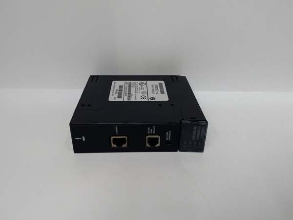
GE IC693CMM321
Field Service Pitfalls: What Rookies Get Wrong
Assuming expandable I/O capacity
You run out of slots at 10 modules and try to add an expansion baseplate. The expansion cable won’t connect—there’s no expansion port on the backplane. You’re stuck with 320 I/O points maximum.
- Field Rule: The IC693CPU323 has NO expansion capability. No expansion baseplate, no remote rack, no expansion connector. You get 10 slots total (including power supply). Plan I/O count carefully—if you need more than 320 points or expansion, use a modular CPU (IC693CPU350+) instead. Don’t waste time trying to connect expansion racks—it’s physically impossible.
Using incompatible PCM or CCM modules
You install a PCM (Programmable Coprocessor Module) or CCM (Cable/Coupler Module) for advanced communication. The module powers up but doesn’t communicate. You spend hours troubleshooting connections when the CPU simply doesn’t support it.
- Field Rule: Embedded CPUs do NOT support PCM or CCM modules. These advanced coprocessors require modular CPUs with higher firmware versions. The IC693CPU323 works with standard I/O modules, analog modules, and basic communication options (Ethernet, Profibus, GBC, GCM, GCM+). PCM/CCM compatibility is explicitly NOT supported—check the manual before installing advanced modules.
Expecting real-time clock functionality
You write logic using time-of-day for scheduling and datalogging. The CPU doesn’t track time correctly—you think the battery is dead when the feature simply doesn’t exist.
- Field Rule: The IC693CPU323 has NO battery-backed clock. The CPU cannot maintain or report real time of day. If power is lost, time information is lost. Use timers and counters for time-based logic. For time-of-day scheduling, use an external real-time clock module or upgrade to a modular CPU with clock support. Don’t write logic that depends on %S clock bits—they don’t exist on this CPU.
Removing power supply and losing program retention
You swap the power supply without planning. After 15 minutes, the battery-backed RAM loses its data and the PLC runs default logic. You blame the new power supply when the backplane’s retention limit was exceeded.
- Field Rule: Battery-backed RAM depends on the power supply’s battery. If the power supply is removed, the backplane’s super capacitor provides only approximately 1 hour of retention. For power supply replacement:
- Prepare new power supply with fresh battery
- Backup program via programming software before removal
- Complete swap within 30 minutes if possible
- Verify program integrity after power-up
- If retention exceeded, reload program from backup
Overlooking SNP slave-only limitation
You try to configure the serial port as an SNP master to initiate communication to another PLC. Nothing works—you think the port is defective when the CPU only supports SNP slave mode.
- Field Rule: The IC693CPU323 serial port supports ONLY SNP slave and SNP-X slave protocols. It cannot initiate communication—it only responds to requests from a master device (HMI, programming software, SCADA). If you need master/client functionality, install an optional communication module (Ethernet, Profibus, etc.). Don’t waste time configuring SNP master on the built-in port—it’s not supported.
Miscalculating discrete I/O limits
You install eight 32-point input modules and expect 256 input points plus 256 output points from another eight modules. The system faults after 320 total points—you exceeded the combined I/O limit.
- Field Rule: Maximum 320 discrete I/O points COMBINED across inputs (%I) and outputs (%Q). This is a hard limit—you cannot exceed 320 total regardless of how many modules are installed. Plan your I/O mix carefully:
- 160 inputs + 160 outputs = 320 total
- 200 inputs + 120 outputs = 320 total
- 320 inputs + 0 outputs = 320 totalAny combination exceeding 320 points will fault. Analog I/O (%AI, %AQ) is separate and doesn’t count toward the 320-point limit.
Failing to account for memory limits with analog I/O
You configure 32 analog input channels and 16 analog output channels. The program exceeds 12 KB memory and won’t download. You strip logic unnecessarily when the problem is analog data handling overhead.
- Field Rule: Analog modules consume register memory (%AI, %AQ) for scaling and data storage. Large analog configurations use significant memory. Calculate memory requirements:
- Each %AI or %AQ word = 2 bytes of register memory
- Scaling blocks and data handling add overhead
- Complex logic with analog operations consumes more program memory than pure discrete logicVerify total program memory usage in programming software before downloading. If approaching 12 KB limit, consider scaling back analog points or upgrading to a CPU with more memory.
Upgrading firmware incorrectly
You attempt to upgrade firmware to gain features and the CPU becomes unresponsive. You’ve bricked a non-replaceable processor—the entire baseplate must be replaced.
- Field Rule: The CPU is embedded and CANNOT be replaced. If firmware upgrade fails, the entire baseplate is non-recoverable. Follow strict upgrade procedures:
- Use only compatible programming software (Logicmaster, VersaPro, Proficy)
- Verify firmware version compatibility BEFORE attempting upgrade
- Ensure stable power during upgrade—use UPS if necessary
- Follow manufacturer’s upgrade steps exactly
- Do NOT interrupt the upgrade processIf unsure, don’t upgrade—the risk is too high for embedded CPUs.
Ignoring backplane current load limits
You install multiple high-current I/O modules (relay outputs, specialty modules). The PLC resets randomly or the power supply faults. You chase grounding issues when backplane current exceeds capacity.
- Field Rule: The CPU draws 430 mA from +5 VDC. Each I/O module adds additional current draw. Calculate total backplane current and verify power supply capacity:
- List all installed modules
- Sum current draw at +5 VDC for each module
- Add CPU’s 430 mA
- Verify total is within power supply ratingHigh-current modules (IC693MDL740, IC693MDL741, etc.) may require power supply upgrades. Never exceed the power supply’s +5 VDC current rating—random resets and faults will occur.
Assuming floating-point math support
You write PID loops with floating-point calculations. The CPU executes math incorrectly or overflows. You think the algorithm is wrong when the CPU simply doesn’t support floating-point operations.
- Field Rule: The IC693CPU323 does NOT support floating-point math. All arithmetic is 16-bit integer (-32768 to +32767). For PID or other math-intensive applications:
- Scale analog values to integers (e.g., multiply by 100 for two-decimal precision)
- Use integer math operations (ADD, SUB, MUL, DIV)
- Watch for overflow—use double-word (32-bit) operations if necessary
- Scale results back to engineering unitsIf floating-point is essential, upgrade to a modular CPU with floating-point support (IC693CPU350+). Don’t try to emulate floating-point with integers for complex algorithms—precision and overflow errors will occur.
Commercial Availability & Pricing Note
Please note: The listed price is for reference only and is not binding. Final pricing and terms are subject to negotiation based on current market conditions and availability.


