
Description
Hard-Numbers: Technical Specifications
- Protocol Support: SRTP (GE Serial Real-Time Protocol over TCP/IP), Modbus TCP (Master/Slave), Ethernet Global Data (EGD)
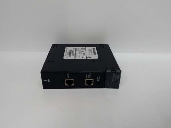
- Port Count: 3 total – 1× AAUI Ethernet port (requires external transceiver + AAUI cable), 1× RS-232 Station Manager port (RJ-11), 1× RS-485 Software Loader port (15-pin D-type)
- Data Rate: 10/100 Mbps Ethernet (auto-sensing via external transceiver)
- Operating Temperature: 0°C to +60°C (32°F to +140°F)
- Storage Temperature: -20°C to +60°C (-4°F to +140°F)
- Isolation Rating: 1500V AC between network and backplane
- Power Draw: 5 VDC from backplane (current consumption varies, verify backplane capacity for dual-module configurations)
- Slot Width: Single slot
- Module Capacity per System: Up to 2 modules per CPU baseplate (not supported in expansion or remote baseplates)
- Maximum Server Connections: 16 concurrent server connections per module
- LED Indicators: OK (module status), LAN (Ethernet traffic), SER (serial port activity), STAT (exception/diagnostic status)
- CPU Compatibility: CPU version 6.50 or higher for full functionality; CPU versions 5.03 to 6.04 support only 1 SRTP server connection
- Network Connection: Requires external SQE-enabled transceiver (GE IC649AEA102/103 or equivalent) plus AAUI cable
- Product Lifecycle Status: Discontinued/Obsolete
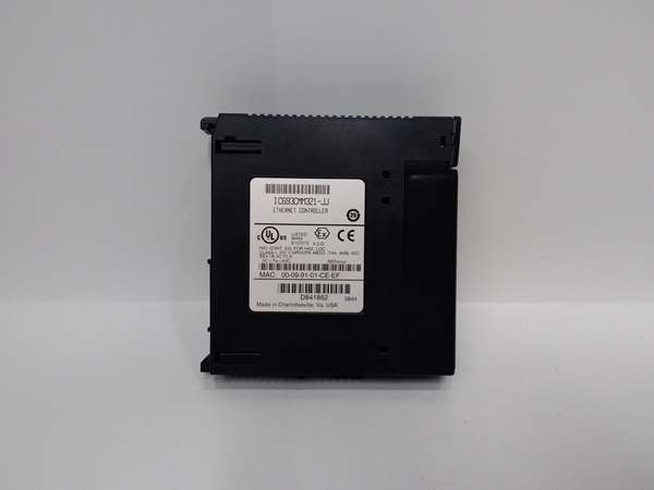
GE IC693CMM321
The Real-World Problem It Solves
Your legacy Series 90-30 is isolated on serial networks while everything else runs on Ethernet. Running serial cable 500 feet to the control room kills signal integrity, and baud rates limit data throughput. You need high-speed TCP/IP connectivity to modern SCADA/HMI systems and real-time data exchange between PLCs without overloading the main processor with network overhead.
Where you’ll typically find it:
- SCADA/HMI integration: Process plants connecting Series 90-30 PLCs to Ethernet-based SCADA systems (Ignition, InduSoft, iFIX) or panel HMIs over TCP/IP for real-time monitoring and control
- Multi-PLC EGD data sharing: Manufacturing facilities with multiple Series 90-30 PLCs sharing data via Ethernet Global Data (EGD) protocol for coordinated motion, material tracking, and distributed control logic
- Modbus TCP to third-party systems: Water treatment, power generation, and oil & gas facilities bridging Series 90-30 to third-party DCS, drives, or instruments via Modbus TCP for protocol translation without external gateways
- Remote programming and diagnostics: Offshore platforms and remote compressor stations requiring Ethernet access for programming software and diagnostic tools without physically connecting serial cables
Bottom line: This module modernizes Series 90-30 connectivity by adding high-speed TCP/IP Ethernet capability with client/server flexibility and multi-protocol support, eliminating serial cable runs and main CPU communication bottlenecks.
Hardware Architecture & Under-the-Hood Logic
The IC693CMM321 contains an onboard coprocessor dedicated to Ethernet communication tasks, independent of the main Series 90-30 CPU. It communicates via the backplane bus to access PLC memory areas while handling all TCP/IP stack execution, protocol framing, and network interface functions externally.
-
Backplane Power-Up and InitializationAt power-on, the module draws 5 VDC from the backplane. Internal diagnostics run (OK LED flashes). The main CPU downloads configuration data (IP address, subnet mask, gateway, protocol assignments, EGD exchange tables). The coprocessor initializes the TCP/IP stack and establishes network parameters. Once configured, the OK LED goes steady. CPU version dictates feature set—6.50+ unlocks full functionality (multiple protocols, 16 server connections). Versions 5.03-6.04 limit to single SRTP server.
-
Ethernet Interface via AAUI and External TransceiverThe module uses an AAUI (Attachment Unit Interface) port, not RJ-45. You must connect an AAUI cable (supplied or GE IC649AAU) to an external SQE-enabled transceiver (GE IC649AEA102/103 or equivalent). The transceiver handles the physical layer conversion to 10/100 Mbps Ethernet (usually RJ-45 or fiber). The AAUI interface itself doesn’t determine speed—the external transceiver does. LAN LED blinks with Ethernet traffic activity.
-
Client Mode: Initiated Communication via COMMREQIn client mode, ladder logic uses the COMMREQ function block to initiate connections to other devices. The coprocessor opens TCP/IP sockets, sends SRTP or Modbus TCP requests, and handles responses. This allows the PLC to push data to SCADA servers or pull data from other PLCs on command. Client mode is CPU-triggered—the coprocessor executes network transactions asynchronously from scan time.
-
Server Mode: Responding to External RequestsIn server mode, the coprocessor listens on configured ports (SRTP default 18245, Modbus TCP 502) and responds to incoming requests. External devices (SCADA, HMIs, other PLCs acting as clients) read or write PLC memory areas. Up to 16 concurrent server connections are supported. Server mode runs continuously—no ladder logic required for basic operation, though EGD exchanges must be configured.
-
Ethernet Global Data (EGD) ConfigurationFor multi-PLC data sharing, EGD creates automatic, cyclic data exchange between configured PLCs. The coprocessor sends/receives EGD frames at configured intervals (10-1000 ms). Each EGD exchange maps PLC memory (%R, %I, %Q, %AI, %AQ) to network data. EGD runs entirely on the coprocessor—no ladder logic intervention. Up to 16 EGD exchanges per module, depending on configuration.
-
Serial Port Functions: Station Manager and Firmware LoaderThe RS-232 RJ-11 Station Manager port provides local access for configuration and diagnostics via GE Station Manager software. The RS-485 15-pin D-type Software Loader port allows firmware upgrades and configuration uploads. SER LED blinks with activity on either serial port. These ports are for maintenance—they don’t handle live process data communication. Use Station Manager to verify network settings, view diagnostics, or perform firmware updates without network access.
-
Dual-Module Configuration and Network SegmentationUp to 2 modules can be installed in the CPU baseplate (not expansion or remote racks). Each module operates independently with its own IP address and protocol configuration. Use dual modules for network segmentation (separate SCADA and control networks), redundancy (critical networks), or increased connection capacity (32 total server connections across 2 modules). Verify backplane power supply supports the load—each module draws 5 VDC current.
-
Restart Button and Diagnostic FunctionsThe front-mounted restart button performs multiple functions: standard restart (reinitializes module), LED test (lights all LEDs for verification), restart and reload mode (reloads configuration from CPU), and restart and enter maintenance utility (accesses diagnostic mode). Access requires the front door open. Use this button for quick module reset without cycling PLC power. STAT LED illuminates during exception conditions or when in maintenance utility.
-
TCP/IP Stack and Protocol HandlingThe coprocessor implements a full TCP/IP stack including ARP, IP, TCP, and UDP layers. SRTP uses TCP for reliable messaging. Modbus TCP uses TCP port 502. EGD can use TCP or UDP depending on configuration (EGD typically uses UDP for low-latency cyclic exchanges). The coprocessor handles all protocol framing, checksum calculation, and retransmission logic. The main CPU never sees raw network traffic—only exchanged data in configured memory areas.
-
Memory Mapping and Data ExchangeThe coprocessor accesses PLC memory via backplane reads/writes. Configured memory tables define which PLC addresses map to network exchanges. For example, Modbus TCP holding register 40001 maps to %R0001. EGD Exchange #1 might send %R0010-%R0050 every 100 ms to a target PLC. All mapping is configured offline via programming software (Logicmaster, VersaPro, Proficy). Data exchange occurs asynchronously—scan time continues uninterrupted.
GE IC693CMM321
Field Service Pitfalls: What Rookies Get Wrong
Assuming RJ-45 Ethernet connection
You look for a standard Ethernet jack on the module faceplate and plug in a Cat5 cable directly. Nothing fits because the module has an AAUI port. You waste time troubleshooting a non-existent hardware fault.
- Field Rule: The IC693CMM311 uses an AAUI port, not RJ-45. You MUST connect an AAUI cable to an external SQE-enabled transceiver (GE IC649AEA102/103 or equivalent). The transceiver converts AAUI to Ethernet (typically RJ-45 or fiber). Never attempt direct wiring—AAUI to RJ-45 adapters are non-standard and unreliable. Use the specified transceiver.
Installing in expansion or remote racks
You mount the module in an expansion baseplate to save CPU rack space. The module powers up but never initializes. LAN communication fails, and you chase firmware or configuration issues when the backplane doesn’t support it.
- Field Rule: Ethernet modules MUST be installed in the CPU baseplate only. Expansion and remote racks do not support IC693CMM321 operation. Up to 2 modules can be installed in the CPU baseplate (CPU 331 or later recommended for dual-module support). Verify rack type before installing—expansion/remote rack installation guarantees failure.
Exceeding 16-server connection limit
You connect 20 HMIs to a single module. Some HMIs randomly disconnect or time out. You blame network switches or cabling when the module has hit its connection limit.
- Field Rule: Maximum 16 concurrent server connections per module. This includes all HMI, SCADA, programming software, and other PLC clients. If you need more connections, install a second module (up to 2 total in CPU baseplate). Each module operates independently, doubling capacity to 32 connections. Monitor active connections via Station Manager diagnostics.
Using old CPU firmware with limited functionality
You install the module in a PLC with CPU firmware version 5.5. You configure multiple protocols and server connections, but only SRTP works. You assume the module is defective when CPU firmware limits features.
- Field Rule: CPU firmware version 6.50 or higher is required for full functionality (multiple protocols, 16 server connections, EGD). CPU versions 5.03 to 6.04 support only 1 SRTP server connection. Verify CPU firmware before configuration. Upgrade firmware if full functionality is required. Incompatible firmware causes partial operation or protocol failures.
Skipping external transceiver power
You connect the AAUI cable to the transceiver but forget to power the transceiver. Network link never establishes, and LAN LED stays dark. You suspect a bad module or cable.
- Field Rule: External transceivers require external power (typically 12-24 VDC). Verify the transceiver’s power supply is connected and operational. The IC693CMM321 powers only the AAUI interface—the transceiver handles the physical layer and needs its own power source. No transceiver power = no Ethernet connection.
Incorrect IP address configuration on dual modules
You install two modules and assign identical IP addresses. Both initialize, but network communication becomes erratic. Some connections work intermittently while others fail completely.
- Field Rule: Each module MUST have a unique IP address, subnet mask, and gateway. Duplicate IPs cause ARP conflicts and unpredictable routing. Use a spreadsheet to track IP assignments in multi-module systems. Verify IP uniqueness via Station Manager before installing in production. Static IP addressing is strongly recommended—DHCP support is limited and unreliable in industrial environments.
Forgetting backplane power capacity check
You install two modules plus high-current I/O modules in a rack with an old power supply. The PLC resets randomly, especially under heavy network load. You chase grounding or noise issues when backplane voltage sags.
- Field Rule: Each IC693CMM321 draws 5 VDC current from the backplane. Two modules double the load. Verify the power supply (IC693PWR321 Rev K or later, IC693PWR322, IC693PWR330) has sufficient capacity for all modules. Calculate total backplane current draw before adding dual modules. Under-rated power supplies cause brownouts and random PLC resets under load.
Missing firmware upgrades for Modbus TCP
You configure Modbus TCP master but the module doesn’t establish connections. You blame protocol settings or remote devices when older firmware lacks full Modbus TCP support.
- Field Rule: Modbus TCP COMMREQ support was added in firmware version 3.10 (July 2000 or later). Pre-3.10 firmware has limited or no Modbus TCP functionality. Verify module firmware version before configuring Modbus TCP. Upgrade firmware via RS-485 Software Loader port if necessary. Old firmware causes Modbus TCP configuration to fail or operate incorrectly.
Hot-swapping the module
You pull the module with power applied to reset network communication. Backplane transients damage the coprocessor or crash the main CPU.
- Field Rule: NEVER hot-swap the IC693CMM321. Power down the PLC rack completely before installing or removing the module. Backplane transients during hot insertion can destroy the coprocessor electronics or corrupt CPU memory. Use the restart button for module resets—only remove modules with power off.
Misdiagnosing LED status
You see the STAT LED illuminated and assume the module has failed. STAT indicates exception events or maintenance mode—not necessarily a hard failure. You replace good modules unnecessarily.
- Field Rule: OK LED: Off = hardware failure or missing CPU. On = normal operation. Blinking during power-up diagnostics. LAN LED: Blinking = Ethernet traffic. Off = no link or activity. SER LED: Blinking = serial port activity. STAT LED: On = exception event or maintenance mode active. Use Station Manager software to read specific exception codes before condemning the module. STAT alone doesn’t indicate hardware failure.
Configuring EGD without understanding cyclic exchange timing
You configure EGD exchanges at 10 ms intervals with large data blocks. Backplane bandwidth saturates, and PLC scan times increase. Network becomes unstable with collision errors.
- Field Rule: EGD exchange intervals must match data size and system performance. Large data blocks (>100 bytes) require longer intervals (100-500 ms). Calculate total EGD bandwidth: (bytes per exchange × exchanges per second). Keep total backplane traffic under 10% of available bandwidth. Test EGD configuration in non-production environments before deployment. Overly aggressive EGD timing destabilizes the entire PLC system.
Commercial Availability & Pricing Note
Please note: The listed price is for reference only and is not binding. Final pricing and terms are subject to negotiation based on current market conditions and availability.


