
Description
Hard-Numbers: Technical Specifications
- Protocol Support: GE Fanuc CCM, Modbus RTU (slave), SNP/SNP-X (client/server)
- Port Count: 2 serial ports (single 25-pin D-shell connector, requires IC693CBL305 Wye cable for separation)
- Port 1 Electrical Standard: RS-232 only
- Port 2 Electrical Standard: RS-232 or RS-485 (RS-422 compatible in RS-485 mode)
- Baud/Data Rate: 300, 600, 1200, 2400, 4800, 9600, 19200 bps (CCM, SNP, RTU)
- Backplane Current Draw: 400 mA at 5 VDC
- Power Source: 5 VDC from PLC backplane (no external power required)
- Slot Width: Single slot
- Module Capacity per System: Up to 4 CMMs in CPU baseplate only (CPU models 331 and later)
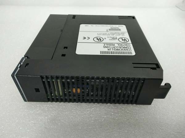
- LED Indicators: MODULE OK, PORT1, PORT2 (also labeled US1, US2 on some revisions)
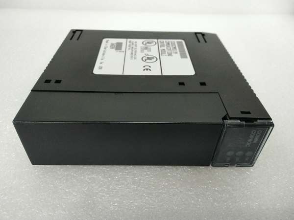
- Connector Type: 25-pin D-shell, female (single connector for both ports)
- Compatible Cable: IC693CBL305 Wye cable (1-foot length, right-angle connector to module)
- Operating Temperature: 0°C to +60°C (32°F to +140°F) (typical Series 90-30 range)
- CPU Compatibility: Modular Series 90-30 CPUs only (NOT compatible with embedded CPUs 311, 313, or 323)
- Product Lifecycle Status: Discontinued/Obsolete

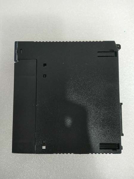
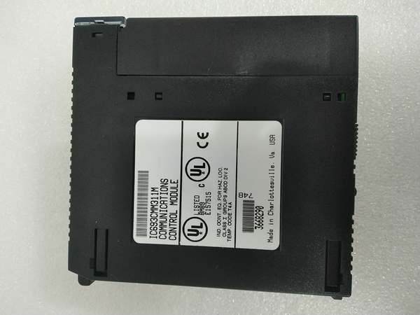
GE IC693CMM311
The Real-World Problem It Solves
Your main CPU is drowning in serial traffic. Every scan cycle gets longer because the processor’s handling Modbus queries, HMI polling, and SNP requests. Communication storms slow down machine logic, miss time-critical interlocks, and trigger watchdogs. You need dedicated hardware to handle the protocol load while keeping CPU scan time tight.
Where you’ll typically find it:
- Modbus RTU integration to DCS/SCADA: Legacy systems connecting Series 90-30 PLCs to Modbus master devices like Wonderware, RSView, or Emerson DeltaV without burdening the main CPU
- SNP protocol expansion: Systems requiring multiple SNP client connections to HMIs, data loggers, or GE programming stations while maintaining low scan times
- CCM multi-PLC networking: Multi-PLC architectures where Series 90-30 controllers need to exchange reference data or share memory via GE’s proprietary CCM protocol without CPU intervention
- Protocol bridging: Applications requiring different protocols on separate ports (CCM on Port 1 for PLC-PLC comms, Modbus RTU on Port 2 for SCADA integration)
Bottom line: This module offloads serial protocol processing from the main CPU, cutting scan time and preventing communication bottlenecks in demanding multi-protocol environments.
Hardware Architecture & Under-the-Hood Logic
The IC693CMM311 contains an onboard microprocessor dedicated solely to serial communication tasks. It communicates with the main Series 90-30 CPU through the backplane bus, sharing PLC memory areas while operating independently for protocol execution. The coprocessor handles framing, error checking, and protocol compliance without CPU intervention.
-
Backplane Initialization and Configuration DownloadThe CMM draws 400 mA at 5 VDC from the backplane. During PLC power-up, the CMM runs self-diagnostics (MODULE OK LED flashes). Once cleared, the main CPU downloads configuration data (protocol assignments, baud rates, memory mapping) via the backplane. The CMM validates configuration and enters operational state (MODULE OK LED steady).
-
Serial Port Signal Routing via Wye CableBoth Port 1 (RS-232 only) and Port 2 (RS-232 or RS-485) share a single 25-pin D-shell connector on the module faceplate. The IC693CBL305 Wye cable splits these signals into two separate connectors labeled PORT 1 and PORT 2. Port 1 uses standard RS-232 pin assignments. Port 2 uses RS-485 signal pins (with RS-422 compatibility) or alternative pins for RS-232 mode. Without the Wye cable, direct wiring is nearly impossible due to shared connector pins.
-
Protocol Processing and Memory AccessThe onboard coprocessor executes selected protocol logic independently. For Modbus RTU slave mode, it responds to read/write requests by accessing configured PLC memory registers (%I, %Q, %R, %AI, %AQ). For SNP, it handles GE’s serial protocol commands. For CCM, it manages peer-to-peer data exchange with other CCM-equipped PLCs. All protocol framing, CRC calculation, and timing are handled by the coprocessor, not the main CPU.
-
Data Exchange with Main CPUThe CMM communicates with the main CPU via backplane messages. It reads configured memory areas (for transmission to external devices) and writes received data back to PLC memory. This exchange occurs asynchronously from CPU scan time, meaning the main CPU is not interrupted for each serial request. The CMM acts as an intelligent buffer between external serial traffic and PLC logic execution.
-
Multi-Module Coordination in CPU BaseplateSystems with CPU models 331 and later can host up to 4 CMMs in the CPU baseplate (not remote or expansion racks). Each CMM operates independently with its own port configurations and protocol assignments. The main CPU manages all CMMs via backplane messaging, distributing communication load across multiple coprocessors. This architecture enables simultaneous multi-protocol communication without CPU overload.
GE IC693CMM311
Field Service Pitfalls: What Rookies Get Wrong
Installing with embedded CPUs
You jam the CMM into a rack with a 311, 313, or 323 embedded CPU. The module powers up but never initializes. You chase firmware issues or bad modules when the CPU doesn’t support it.
- Field Rule: CMMs work ONLY with modular Series 90-30 CPUs. Embedded CPU models (311, 313, 323) lack the backplane infrastructure to support CMMs. Verify CPU model before installing. Upgrade to a modular CPU if you need CMM functionality.
Missing or broken Wye cable
You try to wire directly to the 25-pin connector without the IC693CBL305 Wye cable. You can’t figure out pin assignments because Port 1 and Port 2 signals share pins. Communication fails, or you damage the module.
- Field Rule: Always use the IC693CBL305 Wye cable. It splits the single connector into separate PORT 1 and PORT 2 connectors with correct pin assignments. Never attempt direct wiring—the Wye cable is mandatory for proper operation and signal isolation.
Installing in expansion or remote racks
You mount CMMs in expansion baseplates to save CPU rack space. Modules don’t initialize, and you waste hours troubleshooting backplane communication.
- Field Rule: CMMs MUST be installed in the CPU baseplate only. Expansion and remote racks do not support CMM operation. Up to 4 CMMs can be installed in the CPU baseplate (with CPU 331 or later). Never install CMMs in remote or expansion racks.
Exceeding CPU backplane power budget
You install 4 CMMs plus other high-current modules. The backplane 5V supply sags, and the PLC becomes unstable or resets sporadically.
- Field Rule: Each CMM draws 400 mA at 5 VDC. Four CMMs consume 1.6 A—nearly half the backplane capacity on some power supplies. Calculate total backplane current draw before adding CMMs. Upgrade to higher-capacity power supply if needed. Check CPU power supply ratings (331 or later recommended for multi-CMM systems).
Incorrect RS-485 termination and biasing
You daisy-chain multiple devices on Port 2 RS-485 without termination resistors or bias resistors. Communication works with one device but fails intermittently with multiple nodes due to reflections.
- Field Rule: Always terminate RS-485 buses at both ends with 120-ohm termination resistors. Use bias resistors (typically 560 ohm to +5V, 560 ohm to ground) on networks with many devices. Termination is critical for RS-485 reliability—skipping it causes ghost data and CRC errors.
Firmware version bug with dual SNP slave ports (Pre-4.0)
You run pre-July 1996 firmware on both ports configured as SNP slave. Sending ID value –1 to Cancel Datagram on one port kills datagrams on both ports. Communication fails, and you blame hardware.
- Field Rule: Verify CMM firmware version (Version 4.0 or later released July 1996 fixes the SNP slave bug). If you have pre-4.0 firmware and need dual SNP slave ports, contact GE/Emerson for repair or upgrade. Otherwise, avoid using both ports as SNP slaves simultaneously on old firmware.
Wrong port assignments for protocols
You try to configure Port 1 for RS-485 or Port 2 for CCM/RTU/SNP when it’s set to wrong electrical standard. Port 1 is RS-232 ONLY. Port 2 handles RS-232 or RS-485, but protocol must match electrical standard.
- Field Rule: Port 1: RS-232 ONLY. Port 2: RS-232 or RS-485 (RS-422 compatible). Configure protocols to match these constraints. You cannot run RS-485 on Port 1—physical hardware doesn’t support it. Check jumper settings or configuration software assignments carefully.
Forgetting to restart after configuration changes
You change protocol assignments or baud rates via configuration software but don’t reset the module or PLC. New settings don’t take effect, and you chase communication failures.
- Field Rule: Always perform a PLC reset or cycle power after changing CMM configuration. The coprocessor requires initialization with new parameters to take effect. Use the push button on module (if available) or cycle PLC power to reinitialize communication processor.
Incorrect memory mapping configuration
You map Modbus registers to PLC memory areas that don’t exist or are write-protected. External devices read zeros or get write errors. PLC logic doesn’t see external data.
- Field Rule: Configure memory mappings carefully based on actual PLC memory configuration. Verify %R registers are configured and available. Map Modbus holding registers (4xxxx) to %R, input registers (3xxxx) to %AI, and coils (0xxxx) to %I/%Q. Test mappings with external device before deployment.
Hot-swapping the module
You pull the CMM with power applied to reset communication. Backplane transients fry the coprocessor or crash the main CPU.
- Field Rule: NEVER hot-swap a CMM. Power down the PLC rack completely before installing or removing the module. Backplane transients during hot insertion can destroy the coprocessor electronics or corrupt CPU memory. Cycle power safely—no exceptions.
Misdiagnosing LED status
You see PORT1 or PORT2 LEDs blinking but assume it indicates faults. Blinking means port activity—normal operation. You replace good modules chasing non-existent problems.
- Field Rule: MODULE OK LED: Off = failure, On = normal operation. PORT1 and PORT2 LEDs blink when transmitting or receiving data—this is NORMAL. Steady on or off indicates no activity or fault. Don’t replace modules just because activity LEDs blink. Look at MODULE OK LED for module health.
Commercial Availability & Pricing Note
Please note: The listed price is for reference only and is not binding. Final pricing and terms are subject to negotiation based on current market conditions and availability.


