
Description
Hard-Numbers: Technical Specifications
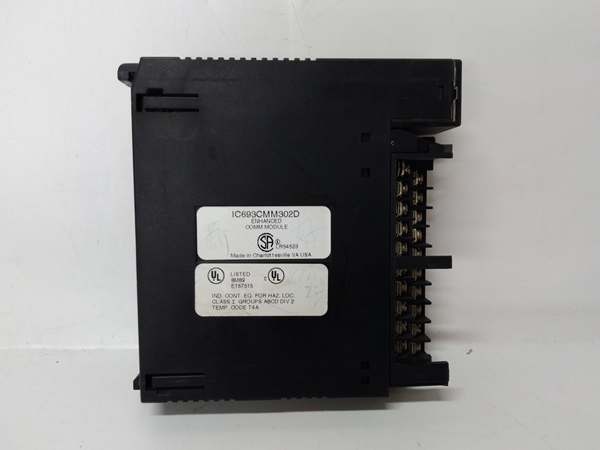
- Module Type: Enhanced Genius Communications Module (GCM+)
- Communication Type: Global Data on Enhanced Genius I/O Serial Bus
- Network Topology: Token-passing peer-to-peer
- Maximum Devices per Module: 31 devices on Genius bus
- Maximum PLC Connections: Up to 2 GCM+ modules per Series 90-30 PLC (up to 62 total devices per controller)
- Global Data Capacity: 128 bytes transmit, 128 bytes receive per GCM+ module
- Supported Registers: %G (Global), %I (Discrete Input), %Q (Discrete Output), %AI (Analog Input), %AQ (Analog Output), %R (Register Memory)
- Slot Width: Single slot
- Slot Assignment: Any slot except CPU slot
- Compatible Baseplates: CPU baseplate, Expansion baseplate, Remote baseplate (CPU baseplate recommended for optimal performance)
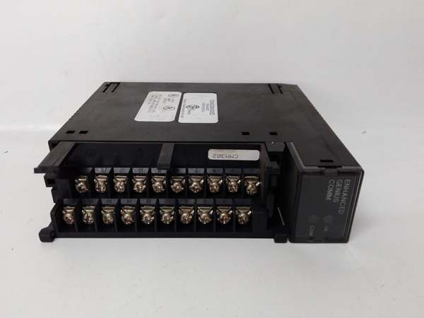
- LED Indicators: OK (module status), COM (bus communication status)
- Configuration Method: Handheld programmer or GE Logicmaster 90-30 software (rel. 3.5 or later required)
- Backplane Current Draw: <300 mA at 5 VDC
- Power Requirements: 5 VDC logic power from backplane
- Dimensions: 4.5 in. × 2.5 in. × 1.5 in. (114 mm × 64 mm × 38 mm)
- Weight: Approximately 0.5 lbs (0.23 kg)
- Operating Temperature: 0°C to 60°C (32°F to 140°F)
- Storage Temperature: -25°C to +70°C (-13°F to +158°F)
- Humidity: 5% to 95% non-condensing
- Vibration/Shock: 0.2 inch displacement (5Hz-10Hz), 1 G (10Hz-200Hz), 5 G (10ms duration)
- Compatible PLC Series: Series 90-30 (primary), Series 90-70, Series Six (with respective Genius Bus Controllers)
- GCM Compatibility: NOT compatible with standard GCM modules (IC693CMM301)
- Data Monitoring: Industrial or personal computer with PCIM card
- Additional Features: Peer-to-peer communication, master-slave communication, I/O emulation, data monitoring from Genius I/O blocks
- Product Lifecycle Status: Discontinued/Obsolete

GE IC693CMM302
The Real-World Problem It Solves
Standard GCM modules (IC693CMM301) limit global data exchange to 256 bits (32 bytes) per module and 7 other devices per bus. Large-scale distributed automation systems with multiple PLCs, extensive Genius I/O networks, and high-volume data sharing requirements hit these limits quickly. The IC693CMM302 GCM+ quadruples global data capacity to 128 bytes per direction and expands device capacity to 31 per module, with support for dual-module configurations enabling up to 62 device connections per PLC.
Where you’ll typically find it:
- Large-scale distributed I/O architectures: Manufacturing plants, material handling systems, and process facilities with extensive Genius I/O blocks and remote drops
- Multi-PLC coordination systems: Applications requiring large data exchange between multiple Series 90-30 PLCs, Series 90-70 PLCs, and various Genius devices
- Data-intensive monitoring: Industrial computers monitoring extensive process data from multiple PLCs and Genius I/O blocks simultaneously
- High-density automation: Systems where standard GCM data capacity and device limits are insufficient for application requirements
Bottom line: The IC693CMM302 delivers enhanced GCM+ capabilities—four times the global data capacity and over four times the device capacity of standard GCM modules, with dual-module support for large-scale Genius networks.
Hardware Architecture & Under-the-Hood Logic
The IC693CMM302 implements the Enhanced Genius Communications protocol (GCM+), an advanced version of the standard Genius bus that provides significantly expanded data capacity and device support. While maintaining token-passing peer-to-peer topology, the GCM+ enhances global data exchange capabilities, supports broader register access, and enables multiple module configurations within a single PLC for segmented network architectures.
-
Enhanced Genius Bus Protocol ArchitectureThe GCM+ implements an advanced version of the Genius Communications protocol:
- Token-passing topology: Each device receives the token in predetermined order
- Peer-to-peer communication: No master device required
- Enhanced device capacity: Up to 31 devices per GCM+ module (vs. 8 on standard GCM)
- Deterministic data exchange: Token rotation time remains predictable and bounded
- Noise-immune design: Differential signaling on shielded twisted pair cable
- Cable specifications: Enhanced cable types supporting longer runs and higher baud ratesThe enhanced protocol maintains deterministic performance while significantly expanding network scale.
-
Expanded Global Data Exchange MechanismGCM+ provides dramatically increased global data capacity:
- 128 bytes (1024 bits) transmit per module (vs. 32 bytes on standard GCM)
- 128 bytes receive per module (vs. 32 bytes on standard GCM)
- Broad register support: %G, %I, %Q, %AI, %AQ, %R memory areas
- Automatic and repeated data transmission without program logic
- All devices on the bus receive all global data simultaneously
- Shared database creation across all participating devicesThe quadrupled data capacity supports complex data sharing scenarios impossible with standard GCM modules.
-
Dual-Module Support and Network SegmentationUnlike standard GCM modules, GCM+ supports multiple modules per PLC:
- Up to 2 GCM+ modules can be installed in a single Series 90-30 PLC
- Each GCM+ module operates its own independent Genius bus
- Enables network segmentation: Separate Genius buses for different system areas
- Maximum device capacity per PLC: Up to 62 devices (31 per module × 2 modules)
- Prevents GCM+ and GCM module mixing in the same PLC
- Enables complex network architectures with isolated segments for different applicationsDual-module capability provides flexible network design and expanded connectivity.
-
Enhanced Application CapabilitiesGCM+ supports multiple communication modes beyond basic global data:
- Data monitoring by industrial or personal computers via PCIM cards
- Peer-to-peer communications among devices on the bus
- Master-slave communications emulating remote I/O
- Data monitoring from Genius I/O blocks (read-only, no control capability)
- Software diagnostics with status bits and fault reporting to Series 90-70 PLCs
- I/O emulation for remote I/O applicationsThe enhanced functionality provides versatile integration options for complex automation systems.
-
Module Placement and Performance OptimizationWhile GCM+ can be installed in multiple baseplate types:
- Compatible with CPU, expansion, and remote baseplates
- CPU baseplate installation recommended for optimal performance
- Sweep impact time depends on PLC model and baseplate location
- CPU baseplate installation minimizes sweep impact and maximizes performance
- Expansion or remote baseplate installation supported but reduces efficiency
- Installation location affects data update latency and system responsivenessProper placement is critical for achieving optimal GCM+ performance.
-
Register Integration and Memory MappingGCM+ provides comprehensive register access:
- %G (Global register): Dedicated global data memory
- %I (Discrete Input): Share discrete input data
- %Q (Discrete Output): Share discrete output data
- %AI (Analog Input): Share analog input data
- %AQ (Analog Output): Share analog output data
- %R (Register Memory): Share register memory data
- Flexible mapping enables sharing virtually any PLC data type on the Genius busThe broad register support enables comprehensive data sharing across the network.
-
LED Status Indicators and DiagnosticsTwo LEDs provide enhanced diagnostic information:
- OK LED: Illuminates when module passes power-up diagnostics and operates properly. Off indicates module failure or fatal power-up error.
- COM LED: Illuminates steadily when bus operates normally. Blinks for intermittent bus errors. Off indicates failed bus or no configuration received from CPU.
- Enhanced diagnostics include status bits and fault reporting
- Software diagnostics support monitoring and troubleshootingLEDs provide immediate visual feedback for operational status.
-
Power and Backplane InterfaceGCM+ draws power from the Series 90-30 backplane:
- Backplane current draw: <300 mA at 5 VDC
- Lower power consumption compared to many communication modules
- Enables multiple modules in same PLC without exceeding power budget
- No external power supply required
- Backplane provides all necessary power and communication interfaceEfficient power design supports dual-module configurations.
-
Compatibility and Integration ConstraintsGCM+ has specific compatibility requirements:
- NOT compatible with standard GCM modules (IC693CMM301) in same PLC
- If GCM is present in a system, GCM+ modules cannot be added
- Compatible with Series 90-70 and Series Six PLCs via respective Genius Bus Controllers
- Requires Logicmaster 90-30 software rel. 3.5 or later for configuration
- PCIM cards enable computer integration for monitoring applicationsCompatibility constraints must be respected for proper system operation.
GE IC693CMM302
Field Service Pitfalls: What Rookies Get Wrong
Mixing GCM and GCM+ in same PLC
You attempt to install an IC693CMM302 (GCM+) in a PLC that already has an IC693CMM301 (GCM). Neither module initializes, communication fails, and you assume the new GCM+ is defective.
- Field Rule: GCM+ modules are NOT compatible with standard GCM modules in the same PLC. You must choose one type per PLC system. If you need GCM+ capabilities, remove all standard GCM modules first. Mixing module types in the same PLC causes complete communication failure.
Exceeding 31-device limit per module
You connect 35 devices to a single GCM+ module bus. The bus becomes unstable, token rotation time increases dramatically, and some devices are ignored or fail to communicate.
- Field Rule: Maximum 31 devices per GCM+ module Genius bus. This includes all devices: PLCs, Genius I/O blocks, remote drops, field control stations, and any other Genius devices. Count all devices—exceeding 31 causes instability and unpredictable communication failures.
Exceeding 2-module limit per PLC
You attempt to install 3 GCM+ modules in a single Series 90-30 PLC. The third module fails to initialize, and you waste time troubleshooting what appears to be a module defect.
- Field Rule: Maximum 2 GCM+ modules per Series 90-30 PLC. Each module requires its own independent Genius bus. If you need more than 62 total device connections (31 per module × 2 modules), use multiple PLCs or network segmentation. The 2-module limit is a hard constraint.
Installing in CPU slot
You try to install the GCM+ module in the dedicated CPU slot. The module doesn’t initialize, or the PLC fails to boot properly.
- Field Rule: GCM+ modules can be installed in any slot EXCEPT the CPU slot. The CPU slot is reserved for the processor module only. Use I/O slots for the GCM+ module. CPU slot installation causes conflicts and prevents proper system initialization.
Ignoring CPU baseplate recommendation
You install the GCM+ module in a remote baseplate to save space in the main rack. Sweep impact time increases, data updates slow down, and you chase performance issues related to the module placement.
- Field Rule: CPU baseplate installation is recommended for optimal GCM+ performance. Sweep impact time depends on PLC model and baseplate location. While expansion and remote baseplates are supported, expect reduced performance. Install in CPU baseplate whenever possible for maximum responsiveness.
Forgetting Logicmaster software version requirement
You attempt to configure the GCM+ module with Logicmaster 90-30 version 3.2. Configuration fails to load, or the module operates with limited functionality.
- Field Rule: GCM+ requires Logicmaster 90-30 software release 3.5 or later for proper configuration. Earlier versions may not recognize the module or may lack GCM+ configuration options. Verify software version before attempting configuration.
Assuming GCM+ controls Genius I/O blocks
You install GCM+ expecting it to control Genius I/O blocks directly. The module can monitor data from the blocks but cannot control outputs, causing unexpected system behavior.
- Field Rule: GCM+ can monitor data from Genius I/O blocks but cannot control them. For I/O control functionality, use appropriate Genius Bus Controllers or other I/O control modules. GCM+ is primarily for global data exchange and monitoring, not direct I/O control.
Incorrect global data configuration
You configure more than 128 bytes of transmit or receive data per GCM+ module. Configuration fails to load, or the module operates with truncated data causing unexpected behavior.
- Field Rule: Maximum 128 bytes (1024 bits) transmit and 128 bytes receive per GCM+ module. While this is quadruple the standard GCM capacity, it’s still a limit. Configure data within these boundaries. If you need more data capacity, install a second GCM+ module in the PLC.
Using incorrect cable type
You attempt to use standard Genius bus cable with GCM+ expecting enhanced performance. Communication fails, or performance degrades compared to expected capabilities.
- Field Rule: GCM+ may require enhanced cable specifications for optimal performance, especially for longer runs or higher baud rates. Consult the GCM+ manual for specific cable requirements. While some standard cables may work, enhanced cables provide the performance characteristics GCM+ is designed for.
Overlooking register support benefits
You configure global data using only %G registers, missing the opportunity to share %I, %Q, %AI, %AQ, and %R data directly. You waste configuration effort manually copying data between register types.
- Field Rule: GCM+ supports broad register access including %G, %I, %Q, %AI, %AQ, and %R. Leverage this capability by configuring data sharing directly from the appropriate register type. Eliminate manual data copying and maximize the value of GCM+ enhanced register integration.
Improper bus termination
You daisy-chain GCM+ devices but don’t terminate the bus properly. Signal reflections cause intermittent communication errors, and the COM LED blinks unpredictably.
- Field Rule: Always terminate the Genius bus at both ends using proper termination resistors specified for GCM+ operation. Unterminated buses cause signal reflections that create ghost data, CRC errors, and communication failures. Proper termination is critical for reliable operation.
Ignoring COM LED blink patterns
You see the COM LED blinking but assume it indicates normal activity. Blinking indicates excessive bus errors, and you ignore the root cause until communication fails completely.
- Field Rule: COM LED should stay ON steadily during normal GCM+ operation. Blinking indicates bus errors from noise, improper wiring, baud rate conflicts, device number conflicts, or termination issues. Address blinking immediately—waiting leads to complete communication failure.
Duplicate device numbers on GCM+ bus
You configure multiple devices with the same device number on the GCM+ bus. Communication fails to initialize, and you chase hardware issues when it’s actually a configuration error.
- Field Rule: Every device on the GCM+ Genius bus requires a unique device number. Document device numbers and verify no duplicates before powering up. The token passing protocol requires unique identifiers—duplicate numbers prevent bus initialization.
Hot-swapping the module
You attempt to insert or remove the GCM+ module with power applied. Backplane transients damage the module or crash the CPU.
- Field Rule: Never hot-swap the IC693CMM302. Power down the PLC rack before installing or removing the module. Backplane transients during hot insertion can destroy module electronics or corrupt CPU memory. Always power down before module changes.
Commercial Availability & Pricing Note
Please note: The listed price is for reference only and is not binding. Final pricing and terms are subject to negotiation based on current market conditions and availability.


