
Description
Hard-Numbers: Technical Specifications
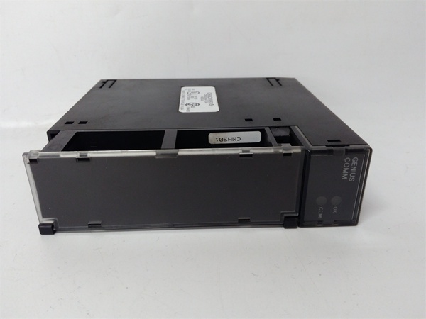
- Module Type: Genius Communications Module (GCM)
- Communication Type: Global Data on Genius I/O Serial Bus
- Network Topology: Token-passing peer-to-peer
- Maximum Devices on Bus: Up to 32 devices (including PLCs, Genius I/O blocks, remote drops, field control I/O stations)
- Maximum PLC Connections: Up to 8 Series 90-30 PLC CPUs per Genius bus
- Global Data Capacity: Up to 256 bits (32 bytes) per communications module, configurable in 32-bit increments
- Per PLC Total: Up to maximum available %G memory in Series 90-30 CPU
- Bus Medium: Standard twisted pair, shielded cable, daisy-chained between devices
- Termination: Required at both ends of the bus
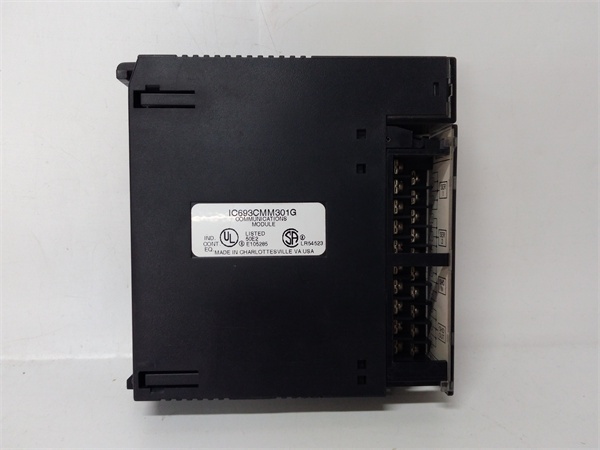
- LED Indicators: OK (module status), COM (bus communication status)
- Configuration Method: Handheld programmer or GE programming software (no DIP switches or jumpers)
- Mounting Location: CPU baseplate, expansion baseplate, or remote baseplate (CPU baseplate recommended for optimal performance)
- Power Requirements: 5 VDC logic power from backplane (approximately 1.2A current draw)
- Dimensions: 4.8 in. × 3.4 in. × 1.5 in. (122 mm × 86 mm × 38 mm)
- Weight: Approximately 0.4 lbs (0.2 kg)
- Operating Temperature: 0°C to 60°C (32°F to 140°F)
- Storage Temperature: -25°C to +70°C (-13°F to +158°F)
- Humidity: 5% to 95% non-condensing
- Vibration/Shock: 0.2 inch displacement (5Hz-10Hz), 1 G (10Hz-200Hz), 5 G (10ms duration)
- Compatible PLC Series: Series 90-30, Series 90-70, Series Six, Series Five (with respective Genius Bus Controllers)
- Host Interface: Computer with PCIM card for data monitoring or programming applications
- Product Lifecycle Status: Discontinued/Obsolete

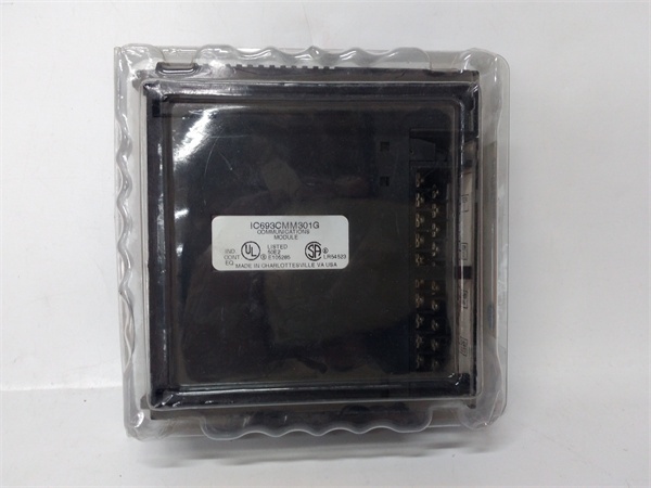
IC693CMM301
The Real-World Problem It Solves
Multiple PLCs need to share data in real-time without the overhead of programmed messaging, protocol conversion, or master-slave polling schemes. The IC693CMM301 implements automatic global data exchange on a deterministic, noise-immune Genius bus—data configured for sharing transmits continuously without requiring program logic, and all participating PLCs receive the shared data automatically. This eliminates complex messaging routines, reduces CPU scan overhead, and provides deterministic data exchange suitable for coordinated control applications.
Where you’ll typically find it:
- Multi-PLC coordinated control: Production lines, material handling systems, and process applications where multiple PLCs must coordinate operations in real-time
- Data sharing across PLC families: Systems integrating Series 90-30 and Series 90-70 PLCs that need to exchange status, setpoints, or production data
- Host computer monitoring: Industrial computers with PCIM cards monitoring process data from multiple PLCs without polling each controller individually
- Genius I/O system integration: PLCs controlling distributed Genius I/O blocks, remote drops, or field control I/O stations over the same bus used for inter-PLC communication
Bottom line: The IC693CMM301 delivers peer-to-peer global data sharing—configure the data once, and it automatically exchanges between all devices on the Genius bus without programmed messaging or CPU overhead.
Hardware Architecture & Under-the-Hood Logic
The IC693CMM301 is an intelligent module that implements the Genius Communications protocol, a token-passing peer-to-peer network optimized for real-time control data exchange. Unlike master-slave networks where devices poll for data, the Genius bus uses deterministic token passing—each device gets the token in turn and transmits its global data. All devices on the bus receive this data simultaneously, creating a shared database accessible to all participants without additional programming.
-
Genius Bus Protocol ArchitectureThe module implements the Genius Communications protocol:
- Token-passing topology: Each device receives the token in a predetermined order
- Peer-to-peer communication: No master device required
- Deterministic data exchange: Token rotation time is predictable and bounded
- Noise-immune design: Differential signaling on shielded twisted pair cable
- Up to 32 devices on a single bus including PLCs, Genius I/O blocks, remote drops, and field control stationsThe token ensures fair access to the bus and guarantees that every device gets transmit time within a known maximum interval.
-
Global Data Exchange MechanismGlobal data is the core communication function:
- Data configured for sharing transmits automatically and repeatedly
- No program logic required for data transmission or reception
- All devices on the bus receive all global data simultaneously
- Up to 256 bits (32 bytes) per IC693CMM301 module
- Configurable in 32-bit increments
- Each Series 90-30 PLC can handle up to its available %G memory for global dataGlobal data creates a shared database across all devices—configure once, and the data automatically appears in all participating PLCs.
-
Module Configuration and SetupThe IC693CMM301 requires software configuration:
- No DIP switches or jumpers on the module
- Configuration via handheld programmer or GE programming software
- Device number assignment (unique identifier on the bus)
- Global data mapping and configuration
- Baud rate selection (must match all devices on the bus)
- Configuration data stored in module non-volatile memoryProper configuration is critical—duplicate device numbers or baud rate mismatches prevent bus communication.
-
Physical Connection and WiringThe Genius bus connects via terminal board on the module front:
- Daisy-chain topology required
- Standard twisted pair, shielded cable
- Termination required at both ends of the bus
- Maximum bus length depends on configuration and number of devices
- Cable specifications must match Genius requirements
- Improper wiring or missing termination causes communication failuresUse only Genius-approved cables and termination resistors.
-
LED Status IndicatorsTwo LEDs provide diagnostic information:
- OK LED: Illuminates when module passes power-up test and is operating properly. If off, module has failed power-up self-test.
- COM LED: Illuminates when PLC has initialized the module and module is receiving bus communications. Normally stays ON during operation. Blinking indicates excessive communication errors (10 errors in 10 seconds from noise, wiring problems, baud rate conflict, or device number conflict). Off indicates no bus communication.These LEDs are the first diagnostic step—check them before diving into complex troubleshooting.
-
Module Placement RecommendationsWhile the module can be installed in CPU, expansion, or remote baseplates:
- CPU baseplate installation recommended for optimal performance
- Expansion or remote baseplate installation supported but may reduce performance
- Local CPU access reduces communication latency for global data updates
- Up to 8 Enhanced Genius Communications Modules can be used in a single Series 90-30 PLC system
- Placement affects data update latency—install in CPU baseplate when possible.
-
Power and Backplane InterfaceThe module draws power from the Series 90-30 backplane:
- 5 VDC logic power from the backplane
- Approximately 1.2A current draw
- Ensure adequate backplane power capacity when multiple modules are installed
- No external power supply required
- Backplane provides all necessary power and communication interfaceHigh-current modules require sufficient power supply headroom.
-
Compatibility and IntegrationThe IC693CMM301 integrates with various GE platforms:
- Series 90-30 PLCs: Direct module installation
- Series 90-70, Series Six, Series Five PLCs: Communicate via respective Genius Bus Controllers
- Computers: PCIM cards enable computer participation on the Genius bus
- Genius I/O blocks, remote drops, field control stations: Direct connection to Genius bus
- Up to 32 total devices on a single Genius busThe module provides cross-platform compatibility within the GE product family.
IC693CMM301
Field Service Pitfalls: What Rookies Get Wrong
Duplicate device numbers on the bus
You configure two modules with the same device number. The bus fails to initialize, COM LEDs blink, and communication never establishes.
- Field Rule: Every device on the Genius bus requires a unique device number. Document device numbers and verify no duplicates before powering up. The token passing protocol requires unique identifiers—if numbers duplicate, the bus cannot operate.
Baud rate mismatch
You configure one module for 153.6 Kbps and another for 76.8 Kbps. Communication fails entirely, and you assume the modules are defective.
- Field Rule: All devices on the Genius bus must use the same baud rate. Verify every device configuration matches. Common baud rates are 153.6 Kbps, 76.8 Kbps, and 38.4 Kbps. Mismatched baud rates prevent any communication.
Missing bus termination
You daisy-chain devices but don’t terminate both ends of the bus. Signal reflections cause intermittent communication errors, and COM LEDs blink unpredictably.
- Field Rule: Always terminate the Genius bus at both ends. Use proper termination resistors specified for the Genius bus. Unterminated buses cause signal reflections that create ghost data, CRC errors, and communication failures.
Using non-shielded cable
You run the Genius bus with unshielded cable to save cost. Communication is unreliable near VFDs or motors, and you chase ground faults that are actually EMI issues.
- Field Rule: Genius bus requires shielded twisted pair cable. The noise-immune design depends on proper shielding. Use only Genius-approved cable with specified impedance. Don’t substitute with generic cable—EMI will destroy communication reliability.
Exceeding device limits
You install 35 devices on a single Genius bus. The bus becomes unstable, token rotation time increases dramatically, and some devices are ignored.
- Field Rule: Maximum 32 devices on a single Genius bus. Count all devices including PLCs, Genius I/O blocks, remote drops, and field control stations. If you need more, split into multiple buses or use network segmentation.
Incorrect global data configuration
You configure global data that exceeds 256 bits per module. The configuration fails to load, or the module operates with truncated data causing unexpected behavior.
- Field Rule: Maximum 256 bits (32 bytes) of global data per IC693CMM301 module. Configure in 32-bit increments. If you need more data sharing, install multiple GCM modules in the PLC or verify CPU %G memory capacity.
Installing in wrong baseplate type
You install the IC693CMM301 in an expansion baseplate that doesn’t support option modules. The module doesn’t initialize, or the bus never establishes communication.
- Field Rule: While the module can be installed in CPU, expansion, or remote baseplates, some baseplate types don’t support communications modules. Verify baseplate compatibility before installation. CPU baseplate installation is recommended for optimal performance.
Ignoring COM LED blink patterns
You see the COM LED blinking but assume it’s normal activity. The blink indicates excessive errors (10 errors in 10 seconds), and you ignore the root cause until communication fails completely.
- Field Rule: COM LED should stay ON during normal operation. Blinking indicates communication errors from noise, improper wiring, baud rate conflict, or device number conflict. Address blinking immediately—waiting leads to complete communication failure.
Hot-swapping the module
You attempt to insert or remove the module with power applied. Backplane transients damage the module or crash the CPU.
- Field Rule: Never hot-swap the IC693CMM301. Power down the PLC rack before installing or removing the module. Backplane transients during hot insertion can destroy module electronics or corrupt CPU memory.
Mixing GCM and GCM+ modules in same PLC
You install both a standard GCM (IC693CMM301) and an enhanced GCM+ module in the same Series 90-30 PLC. They conflict, and neither operates correctly.
- Field Rule: GCM and GCM+ modules cannot be installed in the same Series 90-30 PLC. Choose one type per PLC. GCM+ provides enhanced features but conflicts with standard GCM modules. Document module types and maintain consistency.
Poor grounding and shield termination
You connect the cable shield at only one end or not at all. Noise immunity drops dramatically, and communication fails intermittently in electrically noisy environments.
- Field Rule: Terminate the cable shield properly according to Genius specifications. Shield termination is critical for the noise-immune design. Improper shielding causes EMI susceptibility and communication reliability issues.
Forgetting CPU memory configuration
You configure global data but don’t allocate sufficient %G memory in the Series 90-30 CPU. Configuration loads but data never exchanges properly.
- Field Rule: Verify the Series 90-30 CPU has sufficient %G memory allocated for global data. Per PLC total is limited by available %G memory. Check CPU memory configuration and allocate adequate space for the global data database.
Commercial Availability & Pricing Note
Please note: The listed price is for reference only and is not binding. Final pricing and terms are subject to negotiation based on current market conditions and availability.


