
Description
Hard-Numbers: Technical Specifications
- Slot Count: 5 slots (universal—no CPU slot restriction)
- Baseplate Type: Remote I/O Baseplate (expansion rack)
- Voltage Rating: Powered via I/O expansion cable from main CPU baseplate
- Current Capacity: Receives 5 VDC logic and 24 VDC field power from CPU baseplate power supply
- Isolation: 1500 VAC isolation between logic and field circuits
- Backplane Power Bus: 5 VDC logic power, 24 VDC field power distribution from main rack
- Mounting: DIN rail or panel mount (grounded metal construction)
- Dimensions: Approx. 220 mm × 132 mm × 98 mm (standard depth)
- Weight: Approximately 1.5 kg (3.3 lbs)
- Operating Temperature: 0°C to 60°C (32°F to 140°F)
- Humidity: 5% to 95% non-condensing
- Connector Type: Edge connector for all Series 90-30 I/O module types
- Communication: I/O bus via IC693CBL300 series shielded cables (RS-485 differential signaling)
- Maximum Expansion Distance: 213 meters (700 feet) to last remote baseplate
- Expansion Limits: Up to 7 remote racks (CPUs 350-364) or 4 racks (CPUs 331-341)
- Grounding: Integral grounding studs for proper chassis grounding
- Bus Termination: Supports IC693ACC307 termination plug or built-in termination cables
- Power Supply Compatibility: No local power supply required—receives power from main CPU baseplate

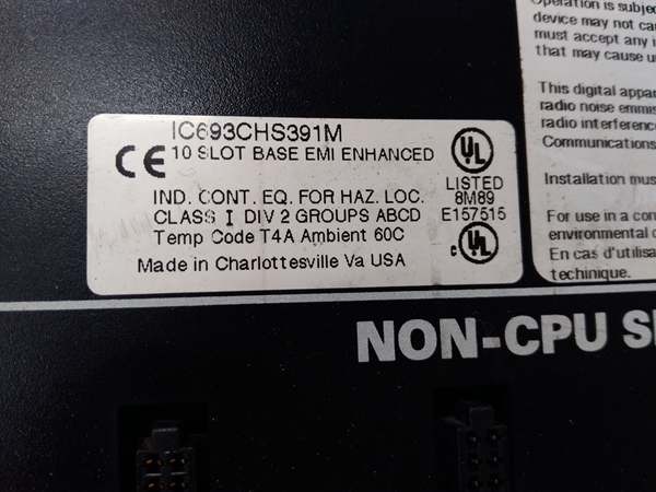
GE IC693CHS391
The Real-World Problem It Solves
Centralized I/O architectures require running every field device wire back to a single control cabinet. This creates massive wire bundles, voltage drop issues, and installation nightmares as distances increase. The IC693CHS398H moves I/O capacity closer to field devices—you can place remote racks near sensors and actuators, run a single shielded cable back to the main CPU rack, and dramatically reduce field wiring complexity while maintaining centralized control logic.
Where you’ll typically find it:
- Distributed control systems: Process plants, manufacturing lines, and material handling systems where I/O points are scattered across large facilities
- Remote equipment skids: Pumps, compressors, and process units located far from the main control room
- Multi-zone applications: Facilities divided into geographically separated control zones with independent I/O requirements
Bottom line: The IC693CHS398H eliminates long field wire runs by placing I/O capacity where it’s needed—distribute your I/O, centralize your control, and cut wiring costs.
Hardware Architecture & Under-the-Hood Logic
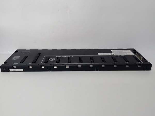
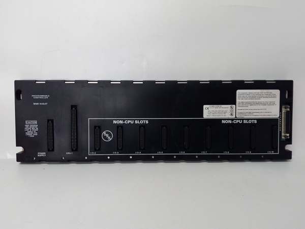
The IC693CHS398H is essentially a 5-slot baseplate designed specifically for remote I/O expansion. It lacks the CPU-specific features of main baseplates (like special power supply mounting or dedicated CPU slots) but provides the same universal slot configuration and electrical characteristics. The critical difference is the I/O bus interface that connects it to the main CPU rack rather than hosting a CPU locally.
-
I/O Bus Communication ArchitectureThe baseplate communicates with the main CPU rack via the Series 90-30 I/O bus:
- Uses RS-485 differential signaling over IC693CBL300 series shielded cables
- Supports daisy-chain topology with multiple remote racks on a single bus
- Data rates up to 153.6 Kbps depending on CPU model and configuration
- Provides noise immunity through differential signaling and shielded cable constructionThe remote baseplate contains the bus receiver circuitry that interprets commands from the main CPU and reports I/O status back.
-
Power Distribution from Main RackRemote baseplates receive power through the I/O expansion cable rather than from local power supplies:
- 5 VDC logic power for module electronics comes from the main CPU baseplate power supply
- 24 VDC field power for I/O modules also originates at the main rack
- The I/O bus cable carries both power and communication signals
- No local power supply required, reducing component count and failure pointsThis distributed power architecture requires careful load calculation across the entire I/O bus to ensure voltage at the last remote rack meets specifications.
-
Universal Slot ConfigurationAll 5 slots are electrically identical and support any Series 90-30 I/O module:
- Discrete input/output modules (IC693MDLxxx series)
- Analog input/output modules (IC693ALGxxx series)
- Communication modules (IC693CMMxxx series)
- Specialty modules (motion control, high-speed counting, etc.)No CPU can be installed in remote baseplates—they’re I/O only. This universal slot design provides maximum flexibility for configuring distributed I/O capacity.
-
Addressing and ConfigurationThe CPU treats remote baseplate slots as part of a continuous addressing scheme:
- Main CPU baseplate slots are addressed first
- Remote baseplate slots follow in daisy-chain order
- Address configuration in CPU software determines which slots map to which I/O points
- Slot numbering in the CPU program includes all slots (main + remote)Configuration software typically includes a “rack and slot” configuration panel where you specify the physical arrangement of baseplates and their contents.
-
Grounding and Shielding SystemProper grounding is critical for reliable remote I/O operation:
- Metal chassis must be grounded to plant earth at each remote location
- I/O bus cable shield must be terminated at both ends (CPU rack and remote rack)
- Ground potential differences between remote locations can create noise issues
- Isolated field commons on modules help prevent ground loop formationThe distributed nature of remote I/O increases grounding complexity compared to centralized systems.
-
Termination RequirementsThe I/O bus must be properly terminated to prevent signal reflections:
- Last remote rack in the daisy chain requires termination
- IC693ACC307 termination plug or IC693CBL302/314 (cables with built-in termination)
- Unterminated buses cause intermittent communication failures
- Termination removes impedance mismatches that cause signal reflectionsMany communication faults in remote I/O systems trace back to missing or improper termination.
-
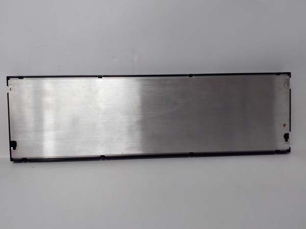
Physical Construction and Environmental ProtectionThe metal chassis provides EMI shielding and heat dissipation:
- Standard 98mm depth fits most industrial enclosures
- DIN rail or panel mounting options
- Grounding studs for chassis ground connection
- Designed for industrial environments with proper enclosure protectionRemote baseplates are often installed in harsher environments than main CPU racks, requiring attention to enclosure IP rating and environmental sealing.
GE IC693CHS391
Field Service Pitfalls: What Rookies Get Wrong
Exceeding distance limits
You chain remote racks beyond the 700-foot limit. Communication becomes intermittent, modules randomly fault, and you spend days chasing what appears to be module failures when it’s actually signal degradation over distance.
- Field Rule: Maximum 700 feet to the last remote rack. Measure actual cable length, not straight-line distance. Use shielded IC693CBL300 series cables. If you need more distance, add network I/O or additional CPUs with their own remote racks.
Overloading the I/O bus power
You fill multiple remote racks with high-current modules. The main CPU baseplate power supply can’t deliver sufficient current through the I/O bus cable. Voltage drops at remote racks cause modules to brown out, fault, or fail unexpectedly.
- Field Rule: Calculate total current draw across all remote slots (5V logic + 24V field). The main rack power supply must handle this total load. Remote racks receive power through the expansion cable—cable resistance causes voltage drop at distant racks. Consider local power supplies for heavy loads or reduce module count per rack.
Missing bus termination
You install remote racks but don’t terminate the I/O bus at the last rack. Signal reflections cause intermittent communication faults that mimic module failures, ground faults, or wiring errors.
- Field Rule: Always terminate the I/O bus at the last remote rack. Use IC693ACC307 termination plug or IC693CBL302/314 (cables with built-in termination). Unterminated buses are the number one cause of “ghost” faults in remote I/O systems.
Improper shield termination
You terminate the I/O bus cable shield at only one end or not at all. Noise immunity drops dramatically, and you get erratic I/O behavior, especially in electrically noisy environments near VFDs or motors.
- Field Rule: Terminate the shield at both the CPU rack and the last remote rack. Use proper shield clamps—not just wire the shield to chassis. Shield continuity is critical for RS-485 communication reliability.
Installing a CPU in remote baseplate
You install a CPU module in a remote baseplate thinking it will add local processing capability. The remote rack doesn’t communicate properly, or you damage the CPU because remote baseplates aren’t designed for local CPUs.
- Field Rule: Remote baseplates are I/O only. No CPU installation. If you need local processing, use a separate main baseplate with its own CPU and I/O. Remote baseplates receive all commands from the main CPU rack.
Daisy-chaining incorrectly
You cable remote racks in a loop or star topology instead of a proper daisy chain. Communication fails, or some racks are ignored because the CPU doesn’t recognize them in the expected configuration.
- Field Rule: Proper daisy chain only. Connect CPU rack to remote rack 1, remote rack 1 to remote rack 2, etc. No loops, no stars, no tee configurations. The I/O bus topology is fixed—deviation causes communication failures.
Ignoring ground potential differences
You install remote racks in separate buildings without addressing ground potential differences. Floating grounds, potential differences, and ground loops cause noise, erratic I/O behavior, or equipment damage.
- Field Rule: Each remote location requires local earth ground. Ground the chassis at each location. Be aware of ground potential differences between buildings—use fiber optic isolation or proper isolation techniques if ground potential differences are significant.
Exceeding expansion limits
You chain 8 remote racks to a CPU 350-364. The 8th rack is ignored, and you waste hours troubleshooting why half your I/O points are missing from the system.
- Field Rule: Respect CPU expansion limits. CPUs 350-364 support maximum 7 remote baseplates. CPUs 331-341 support 4. Document rack count and CPU model. If you need more, use network I/O or additional CPUs.
Using incorrect cable type
You use unshielded or non-IC693CBL300 series cable for I/O bus connections. Communication fails intermittently, especially in noisy environments, and you blame the baseplates or modules when it’s actually the cable.
- Field Rule: Use only IC693CBL300 series shielded cables. These are specifically designed for the I/O bus with proper shielding, impedance, and connector types. Don’t substitute generic cable—communication reliability depends on proper cable construction.
Forgetting configuration update
You add remote baseplates physically but don’t update the CPU software configuration. The new slots remain unrecognized, and I/O points mapped to the new racks don’t function.
- Field Rule: Update hardware configuration in CPU software after physical changes. Add the new baseplates and slots to the I/O table. Download updated configuration. Physical changes without software updates result in unrecognized hardware.
Poor environmental protection
You install remote baseplates in unsealed enclosures exposed to dust, moisture, or temperature extremes. Premature module failure, corrosion, and intermittent faults plague the system.
- Field Rule: Remote baseplates need proper enclosure protection. Maintain IP rating appropriate for the environment. Provide ventilation for heat dissipation. Consider NEMA 4 or 12 enclosures for harsh environments. Remote racks often face worse conditions than main CPU racks.
Commercial Availability & Pricing Note
Please note: The listed price is for reference only and is not binding. Final pricing and terms are subject to negotiation based on current market conditions and availability.


