
Description
Section 3. Product Introduction
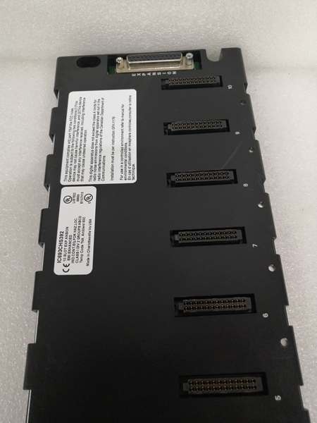
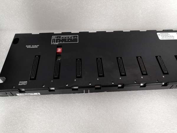
The GE IC693CHS397L is a 5-slot expansion baseplate for Series 90-30 PLC systems with factory-installed mounting brackets. It provides electrical connectivity for I/O and power modules without CPU slot, connecting to main rack via expansion cable for I/O capacity extension.
This variant includes pre-installed mounting hardware—simplifying field installation. Rated for 0–60°C operating range with IP20 protection. Supports cable runs up to 50 ft to main CPU rack—verify with OEM datasheet.
Section 4. Key Technical Specifications
| Parameter | Value |
|---|---|
| Module Type | Expansion I/O Base with Mounting |
| Baseplate Option | Expansion (no CPU slot) |
| Number of Slots | 5 (0 CPU + 5 I/O) |
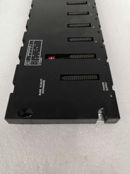
| Power Supply Slot | 1 (leftmost, unnumbered) |
| Connector | 25-Pin Female (right side) |
| Internal Power Used | 420 mA @ 5 VDC |
| Dimensions | 17.44 x 5.12 x 5.59 in. (W x H x D) |
| Weight | 3.00 lbs (1.36 kg) with brackets |
| Mounting | Panel mount with integrated brackets |
| Default Rack Address | Sequential (1–7, software configurable) |
| Expansion Support | Daisy-chain from main CPU rack |
| Protection Rating | IP20 (open enclosure, dust-sensitive) |
Section 5. Quality Control Process
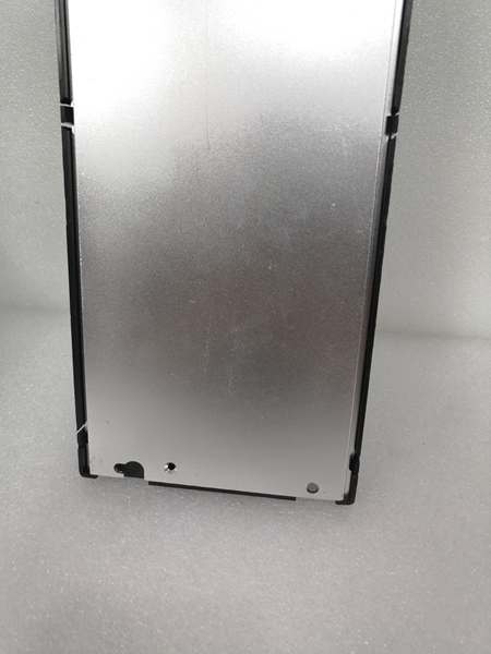
1. Incoming VerificationTrace source documentation and cross-check serial numbers against OEM records. Visual inspection for corrosion, impact damage, or connector wear. Verify mounting bracket integrity and mounting hole alignment.
2. Live Functional TestPower-on with verified power supply module in left slot. Verify I/O module detection via main CPU rack RS-232 handshake. Run continuous load simulation >24 hours while logging internal temperature—thermocouple on backplane near Slot 3.
3. Electrical Parameter TestMeasure insulation resistance with 500 V Megger; must exceed 10 MΩ. Check ground continuity from mounting tabs to backplane ground plane. Verify 5 VDC rail tolerance ±5% under full load.
4. Firmware VerificationNo firmware on baseplate itself—but photograph DIP switch positions and document revision codes. Label bracket orientation and rack address configuration clearly.
5. Final QC & PackagingSeal in anti-static bag with desiccant pack. Apply QC Passed label with date and technician initials. Double-box with foam inserts for shipment—brackets require extra padding.
Section 6. Replacement Pitfall Guide
❗ Rack Address ConflictsThe GE IC693CHS397L requires sequential rack addressing in expansion chains. Default addresses often clash with existing configurations. Verify your current rack numbering before installation—duplicates cause bus contention errors.
❗ Cable Length LimitsExpansion baseplates support cable runs up to 50 ft only—exceeding this causes signal integrity issues. Use shielded cable with proper termination at both ends. Measure your actual run length carefully; oversizing cable causes unnecessary signal loss.
❗ Power Supply OversizingExpansion racks lack local CPU monitoring—power must support all I/O modules independently. Calculate total current draw at 5 VDC, then add 30% headroom for margin. Undersized supplies cause voltage drop during high-load states.
❗ DIP Switch MisconfigurationFactory DIP switch settings rarely match your system requirements. Document original settings before changing. Verify rack address and termination resistor settings—wrong configuration prevents proper communication.
❗ Mounting Bracket IssuesIntegrated brackets on the GE IC693CHS397L may not align with pre-existing panel cutouts. Measure your mounting hole spacing before ordering. Retrofitting standard IC693CHS397 brackets in the field adds hours.
Keep these in mind and you’ll cut 90% of rework time.

GE IC693CHS392
Section 7. Compatibility Matrix & Benchmarks
Compatibility Matrix
- IC693CHS397L → IC693CHS397 (no brackets) : Needs Adaptation — Same form factor, requires separate mounting kit
- IC693CHS397L → IC693CHS397C/E : Direct — Same form factor with brackets, verify revision code
- IC693CHS397L → IC693CHS391 (10-slot CPU) : Incompatible — Different form factor and slot type
- IC693CHS397L → IC693CHS393 (5-slot remote) : Needs Adaptation — Different protocol, cable length limits differ
- IC693CHS397L → IC693CHS394 (10-slot expansion) : Needs Adaptation — Same expansion type, different slot count
- IC693CHS397L → IC693CPU331/340/350 : Not Direct — Requires main CPU baseplate for connection
Benchmarks
- Scan cycle: 2–8 ms (simulated load, 32 I/O points, main CPU 350)
- Comms throughput: 115.2 kbps (RS-232 serial, Protocol: SNP)
- Cable length: Up to 50 ft (shielded, properly terminated)
- Backplane bus speed: 8 MHz (Series 90-30 standard)
- I/O response time: 0.5–1 ms (expansion rack to CPU, 25 ft cable)


