
Description
Hard-Numbers: Technical Specifications
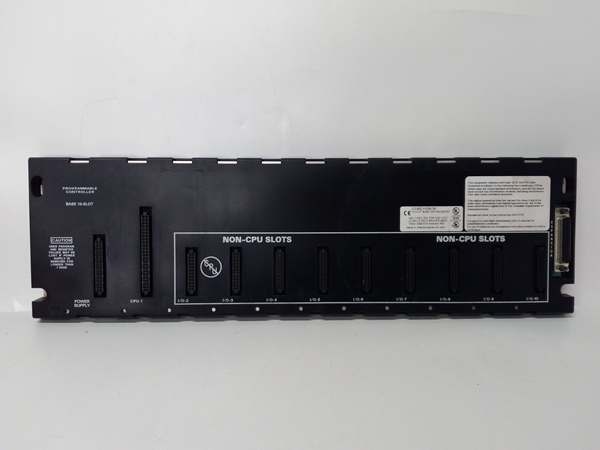
- Slot Count: 10 slots (two 5-slot baseplates configured as unified rack)
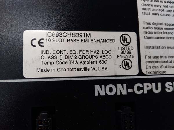
- Baseplate Components: IC693CHS391 (5-slot baseplate) + expansion assembly kit
- Voltage Rating: 115/230 VAC (50/60 Hz) or 24 VDC power supply input
- Current Capacity: 10 Amps (with IC690PWR124) or 5 Amps (with IC690PWR024)
- Isolation: 1500 VAC isolation between logic and field circuits
- Backplane Power Bus: 5 VDC logic power, 24 VDC field power distribution
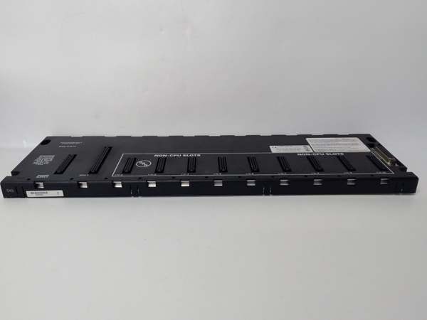
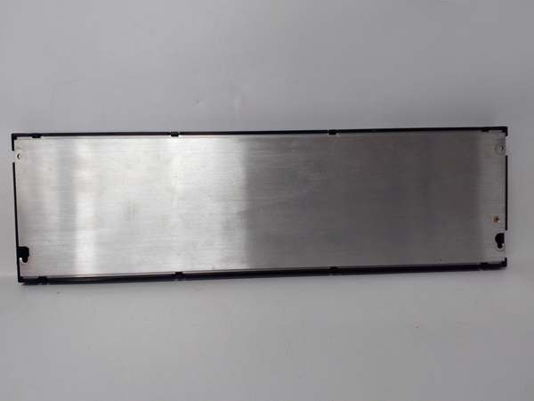
- Mounting: DIN rail or panel mount (grounded metal construction)
- Dimensions: Approx. 420 mm × 132 mm × 98 mm (combined 10-slot assembly)
- Weight: Approximately 3.0 kg (6.6 lbs) combined assembly
- Operating Temperature: 0°C to 60°C (32°F to 140°F)
- Humidity: 5% to 95% non-condensing
- Connector Type: Edge connector for all Series 90-30 module types
- Interconnection: Includes bracketing system and backplane interconnect cable
- Power Supply Compatibility: IC693PWRxxx series power supplies (single supply powers entire 10-slot assembly)
- Expansion Capability: Supports baseplate expansion via IC693CBL300 series cables
- Grounding: Integral grounding studs on both baseplate sections
- Product Lifecycle Status: Active

GE IC693CHS391
The Real-World Problem It Solves
Standard 5-slot baseplates fill up fast when you’re running 32-point I/O modules or mixing high-density digital with analog modules. Once you hit five slots, your options are ugly: add another rack and run expansion cables (expensive, adds failure points), or upgrade to a 10-slot rack from scratch (downtime, rewiring). The IC693CHS391M lets you bolt a second 5-slot section onto your existing IC693CHS391 and create a unified 10-slot rack without ripping out your existing wiring or buying a whole new chassis.
Where you’ll typically find it:
- High-density I/O concentration points: Central control rooms or MCC enclosures where you need 8-10 modules worth of discrete and analog I/O feeding from a single location
- Analog-heavy applications: Process control racks where analog modules, thermocouple cards, and RTD inputs eat up slots fast and you need more room than a standard 5-slot provides
- Retrofit upgrades: Expanding existing 5-slot installations that have run out of space without requiring a complete system replacement or cabinet redesign
Bottom line: The IC693CHS391M doubles your I/O capacity in a single rack by combining two 5-slot baseplates into a unified 10-slot assembly—no new cabinet, no new power supply, no massive rewiring job.
Hardware Architecture & Under-the-Hood Logic
The IC693CHS391M is essentially two IC693CHS391 5-slot baseplates engineered to work together as one cohesive unit. You get the metal hardware to bolt them together, a backplane interconnect cable that ties the two backplanes electrically, and proper grounding straps to ensure both chassis sections share the same reference. From the module’s perspective, it’s just a 10-slot backplane—no different than if you’d bought a native 10-slot rack from day one.
-
Dual Baseplate ArchitectureThe kit ships as two separate 5-slot baseplates that you assemble in the field:
- Primary baseplate: IC693CHS391 (your existing or new 5-slot unit)
- Expansion baseplate: Additional IC693CHS391 included in kitThey bolt together side-by-side using supplied brackets, creating a mechanically rigid 10-slot assembly. The alignment pins ensure the backplane edges line up perfectly for module insertion.
-
Backplane Interconnection SystemA flat cable assembly connects the two backplanes electrically. This cable carries:
- 5 VDC logic power from primary baseplate to expansion
- Data bus signals ensuring both backplanes communicate as one
- Address and identification signals across the unified rackThe interconnect cable is polarity-keyed and only fits one way—you can’t reverse it and smoke the backplanes.
-
Power Distribution LogicOne power supply powers the entire 10-slot assembly. Whether it’s a 5-amp (IC690PWR024) or 10-amp (IC690PWR124) unit, it connects to the primary baseplate. Power flows through the backplane interconnect cable to the expansion baseplate, distributing 5 VDC logic power and 24 VDC field power to all 10 slots. The backplane handles the current division—you just need to size your supply for the total module load across both baseplate sections.
-
Grounding and Bonding SystemBoth baseplate sections have their own grounding studs, but the kit includes bonding straps to tie them together. This ensures both chassis sections share identical ground reference. Without the bonding strap, you could end up with ground potential differences between the two baseplates, creating noise, erratic I/O behavior, or safety hazards.
-
Slot UniversalityAny Series 90-30 module fits any slot in either baseplate section. No CPU-only slots, no special expansion slots—10 identical slots in a unified backplane. You can mount a CPU in slot 1 of the primary baseplate, fill slots 2-5 with I/O, and use slots 6-10 in the expansion for additional I/O. The backplane treats all 10 slots as one contiguous block.
-
Physical Construction and MountingWhen assembled, the unit is essentially a 10-slot rack. It mounts to DIN rail or panel via the primary baseplate’s mounting provisions. The bonding brackets create a rigid mechanical structure that resists vibration. Both baseplate sections have metal chassis for heat dissipation and EMI shielding. The combined dimensions make it a substantial assembly—ensure your cabinet depth and mounting structure can handle the weight and footprint.
-
Module Addressing ImplicationsThe CPU sees a unified 10-slot backplane, not two separate 5-slot racks. Slot addressing is continuous 1-10 across the assembly. This matters for configuration software and program addressing—slots 1-5 are in the primary baseplate, slots 6-10 are in the expansion baseplate, but the CPU doesn’t care. It just sees 10 slots worth of I/O to manage.
GE IC693CHS391
Field Service Pitfalls: What Rookies Get Wrong
Improper backplane interconnection
You bolt the two baseplates together but forget to install the backplane interconnect cable. The expansion baseplate powers up (if it has its own supply) or stays dead (if powered via interconnect), but no communication occurs between the two halves. The CPU sees slots 1-5, slots 6-10 are invisible, and you’re troubleshooting why half your rack doesn’t respond.
- Field Rule: The backplane interconnect cable is mandatory for unified operation. Install it before powering up. The cable is keyed—align the polarity markers. Don’t try to power both baseplates independently without the interconnect cable or you’ll address conflicts and communication failures.
Missing bonding strap installation
You install both baseplates and power everything up, but you don’t install the grounding bonding strap between the two chassis sections. You get ground loops, noise-induced I/O faults, or worst case—safety hazards with potential differences between chassis.
- Field Rule: Install the bonding strap that comes with the kit. It connects the two chassis grounds together, ensuring identical reference. Without it, you’re asking for trouble. Ground both baseplates individually to plant ground AND bond them together.
Overloading a single power supply
You fill all 10 slots with high-current output modules but power the rack with a 5-amp supply (IC690PWR024). The supply sags under load, modules brown out or fault, and you’re chasing what looks like module failures when it’s actually capacity starvation.
- Field Rule: Calculate total module current draw across all 10 slots. 32-point output modules, analog cards, and specialty modules all pull power. Size your supply for the combined load plus 20% margin. For high-density racks, upgrade to IC690PWR124 (10 amp) or consider split powering if you’re exceeding limits.
Improper mechanical alignment
You bolt the two baseplates together but don’t use the alignment pins. The backplanes end up slightly misaligned, modules won’t seat fully, and you’re forcing connectors into edge connectors that don’t line up.
- Field Rule: Use the alignment pins provided in the kit. They ensure the backplane edges line up perfectly. Don’t rely on just the brackets—alignment pins are there for a reason. Verify modules seat flush across both baseplate sections before tightening everything down.
Incorrect power supply placement
You mount the power supply on the expansion baseplate instead of the primary baseplate. The backplane interconnect cable isn’t designed to power the primary from the expansion, or you create current flow paths that exceed the cable’s rating.
- Field Rule: Power supply connects to the primary baseplate (IC693CHS391 base unit). The interconnect cable distributes power to the expansion baseplate. Don’t reverse this relationship. The cable and backplane architecture are designed for one-way power flow from primary to expansion.
Forgetting expansion termination
You use this 10-slot assembly as an expansion rack for a remote I/O application but forget termination plug. Signal reflections cause intermittent I/O faults, especially at higher bus speeds.
- Field Rule: If this 10-slot unit is the last rack in an expansion chain, terminate the I/O bus. Use IC693ACC307 Terminator Plug or IC693CBL302/314 (15m cable with built-in termination). Never leave the bus unterminated—reflections cause data errors.
Hot-swapping baseplates or interconnect cable
You try to add the expansion baseplate to a running system without killing power. Backplane transients crash the CPU, brown out existing modules, or damage the interconnect cable or backplane traces.
- Field Rule: Kill all power before assembling or modifying the baseplate system. Remove the power supply or switch off mains. Verify zero voltage before touching backplane connections. These aren’t hot-swappable components—you’ll eventually pay for smoked boards.
Ignoring cabinet space requirements
You install a 10-slot assembly into a cabinet designed for a 5-slot rack. The unit doesn’t fit depth-wise, the door won’t close, or you’re forcing components into spaces they weren’t designed for.
- Field Rule: A 10-slot assembly is roughly twice the footprint of a 5-slot. Measure your cabinet depth, door clearance, and mounting structure before ordering. Don’t assume a 5-slot cabinet can handle the 10-slot upgrade without modification.
Incorrect software configuration
You expand from 5 slots to 10 slots but don’t update your hardware configuration in the PLC software. The CPU only recognizes slots 1-5, and slots 6-10 are dead in the program even though they’re physically present and powered.
- Field Rule: Update your hardware configuration after physical expansion. Add slots 6-10 to the I/O table, configure modules in the software, and download updated configuration to the CPU. Physical changes require software updates—don’t assume the CPU auto-detects the new slots.
Mixing incompatible modules
You install a VersaMax or RX3i module into this Series 90-30 baseplate because “it fits.” The pinout doesn’t match, connector doesn’t seat, and you either force it (bad) or waste time troubleshooting why the module won’t power up.
- Field Rule: IC693CHS391M is Series 90-30 only. No VersaMax, no RX3i, no mixed systems. Verify module series before installation. If you need multiple PLC families, use separate baseplates or communicate via network, not by jamming incompatible hardware into the wrong backplane.
Commercial Availability & Pricing Note
Please note: The listed price is for reference only and is not binding. Final pricing and terms are subject to negotiation based on current market conditions and availability.


