
Description
Hard-Numbers: Technical Specifications
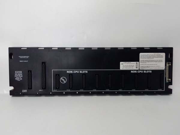
- Slot Count: 5 slots (expandable to 10 slots with IC693CHS391 expansion kit)
- Baseplate Type: Universal Backplane (supports all Series 90-30 modules)
- Voltage Rating: 115/230 VAC (50/60 Hz) or 24 VDC power supply input
- Current Capacity: 10 Amps (with IC690PWR124) or 5 Amps (with IC690PWR024)
- Isolation: 1500 VAC isolation between logic and field circuits
- Backplane Power Bus: 5 VDC logic power, 24 VDC field power distribution
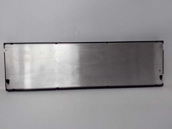
- Mounting: DIN rail or panel mount (grounded metal construction)
- Dimensions: Approx. 210 mm × 132 mm × 98 mm (varies by mounting configuration)
- Weight: Approximately 1.5 kg (3.3 lbs)
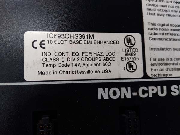
- Operating Temperature: 0°C to 60°C (32°F to 140°F)
- Humidity: 5% to 95% non-condensing
- Connector Type: Edge connector for all module types
- Power Supply Compatibility: IC693PWRxxx series power supplies
- Expansion Capability: Supports baseplate expansion via IC693CBL300 series cables
- Grounding: Integral grounding studs for proper chassis grounding
- Product Lifecycle Status: Active

GE IC693CHS391
The Real-World Problem It Solves
Control systems often need I/O distributed throughout a facility rather than centralized in one massive rack. Running hundreds of individual wires back to a main rack creates cable management nightmares, voltage drops, and single points of failure that can take down your entire process. The IC693CHS391 gives you a compact 5-slot expansion rack that you can mount right where the field devices live, dramatically reducing wiring runs and localizing I/O faults to specific process areas.
Where you’ll typically find it:
- Remote I/O skids: Small process units, pump stations, or valve islands that need 5-10 I/O cards locally but communicate back to main PLC via baseplate expansion cables
- Machine control panels: Compact equipment packages where a full 10-slot rack is overkill but you need more than a couple of I/O modules close to the action
- I/O concentration points: Terminal equipment buildings, MCC rooms, or field enclosures where consolidating I/O in one compact rack beats running individual field wires back to control room
Bottom line: The IC693CHS391 lets you push I/O out to where it’s actually needed—5 slots of expansion capability in a grounded metal chassis that supports standard Series 90-30 modules and power supplies.
Hardware Architecture & Under-the-Hood Logic
The IC693CHS391 is a passive backplane with active power distribution. It doesn’t process data—that’s what modules do—but it provides the physical and electrical foundation for everything else. The metal chassis grounds your I/O commons, supplies logic and field power to modules via the backplane bus, and gives you a DIN-rail-ready enclosure that can take industrial vibration and heat.
-
Backplane Signal ArchitectureEach of the 5 slots contains an edge connector that mates with any Series 90-30 module—CPU, I/O, communications, whatever. The backplane carries:
- 5 VDC logic power for module electronics
- 24 VDC field power for I/O circuits
- Data bus for CPU-module communication
- Module identification and addressing signalsNo switching, no routing logic, just copper traces distributing power and data to whoever plugs in.
-
Power Supply InterfaceThe baseplate accepts standard Series 90-30 power supplies (IC693PWR321, PWR322, PWR330, etc.). Power supply connects to the backplane, which then distributes 5 VDC logic power and 24 VDC field power to all slots. This means every module gets clean, regulated power without individual power wiring—modules just plug in and run.
-
Common Grounding SystemThe metal chassis is your ground reference. Integral grounding studs provide connection points for safety ground, and the backplane distributes I/O commons to modules. When you install an output module with groups A, B, C, D, each group’s common connects through the backplane to chassis ground if you’ve configured it that way. This prevents floating commons and ground loops that cause erratic I/O behavior.
-
Isolation and Noise ImmunityThe backplane provides 1500 VAC isolation between logic circuits (CPU, internal module electronics) and field circuits (the I/O points themselves). This means a 24VDC short on your field wiring doesn’t fry your CPU or crash your logic—critical when you’re dealing with inductive loads, welding equipment, or anything that can spike voltage on the field side.
-
Baseplate Expansion CapabilityThe IC693CHS391 is a 5-slot standalone, but it’s designed to work as an expansion baseplate. You can chain it to a CPU baseplate using IC693CBL300 series expansion cables. This turns it into a remote I/O rack that communicates over the I/O bus back to the main CPU. The backplane handles all the signaling—you just mount it where you need I/O and run the expansion cable.
-
Slot UniversalityAny Series 90-30 module fits any slot. No reserved CPU slot, no special I/O slots, no compatibility matrix to memorize. You can mount a CPU in slot 1 and I/O in slots 2-5, or fill all five slots with I/O if this is a remote rack controlled via expansion cable. The backplane doesn’t care—it just supplies power and carries data.
-
Physical ConstructionMetal chassis absorbs vibration, dissipates heat, and provides EMI shielding. The baseplate mounts to DIN rail or directly to panel. Ground studs on the chassis connect to your plant ground system—critical for noise immunity and personnel safety. The whole assembly is designed to survive 60°C ambient temperature and industrial shock and vibration per IEC standards.
GE IC693CHS391
Field Service Pitfalls: What Rookies Get Wrong
Installing non-Series 90-30 modules
You try to plug a VersaMax or RX3i module into this baseplate because “it’s GE, right?” The pinout doesn’t match, the connector doesn’t seat, and you either force it (bad idea) or waste hours troubleshooting why the module won’t power up.
- Field Rule: IC693CHS391 is Series 90-30 only. No VersaMax, no RX3i, no PACSystems modules except 90-30 series. Verify module series before mounting. If you need mixed systems, use separate baseplates or communicate via network, not by jamming incompatible hardware into the wrong backplane.
Improper chassis grounding
You mount the baseplate to a plastic backplate or painted surface without scraping paint to bare metal. The chassis floats, noise immunity goes to zero, and you’re chasing ghosts—inputs flicker, outputs fire randomly, modules fault for no reason.
- Field Rule: The metal chassis must connect to plant ground. Scrape paint to bare metal at mounting points, use star washers if needed, and connect to your ground bus. No ground paint isolation, no floating racks. The ground stud exists for a reason—use it.
Overloading the power supply
You fill all five slots with high-current output modules and power the rack with a 5-amp supply (IC690PWR024). The supply sags, modules brown out, and worst case—you get intermittent faults or complete shutdown under load.
- Field Rule: Calculate total module current draw against your power supply capacity. Most 32-point output modules draw significant 24VDC field power. Add up all modules in the rack, add 20% margin, and size your supply accordingly. If you’re pushing limits, upgrade to IC690PWR124 (10 amp) or split the load across multiple racks.
Ignoring isolation ratings
You wire 120VAC field devices directly to a 24VDC-rated module or backplane without external isolation. You smoke the module, damage the backplane traces, and create a safety hazard.
- Field Rule: The backplane provides isolation between logic and field circuits, but that doesn’t mean you can ignore voltage ratings. Match field voltage to module voltage. 24VDC modules for 24VDC devices, 120VAC modules for 120VAC devices. Never mix. The 1500VAC isolation rating is there to protect your logic if something goes wrong—not to enable voltage mismatches.
Hot-swapping modules
You pull or insert modules while the baseplate has power. You induce backplane transients, brown out adjacent modules, or worst case—damage the power supply or module electronics.
- Field Rule: Kill all power before touching modules. Remove the power supply or switch off the mains. Verify zero voltage on the backplane with a multimeter. Never hot-swap Series 90-30 modules—these aren’t designed for it, and you’ll eventually pay for a new board.
Incorrect expansion cabling
You chain this baseplate to a CPU rack using wrong cable or reverse the connectors. The I/O bus fails, the remote rack doesn’t communicate, and you’re tracing 500 feet of cable for a wiring error.
- Field Rule: Use IC693CBL300 series cables for baseplate expansion. Respect length limits—1m, 2m, 8m, 15m options exist for a reason. Never exceed 15m total for local expansion or 700ft for remote I/O. Terminate the last rack with IC693ACC307. Verify cable orientation—male to CPU, male to first expansion, daisy-chain correctly.
Mounting in high-heat environments
You install this baseplate in an enclosure that hits 65°C ambient. The backplane runs hot, modules derate or fault, and you get premature failure.
- Field Rule: IC693CHS391 is rated to 60°C ambient. If your enclosure runs hotter, add ventilation, move the rack, or use forced cooling. Don’t ignore temperature ratings—heat kills electronics faster than anything else in industrial environments.
Mixing commons incorrectly
You wire output commons back-to-back or connect groups A and B together on the terminal block expecting the backplane to isolate them. You create ground loops, cause shared faults, or worst case—short your power supply.
- Field Rule: Each I/O group is isolated at the module level. The backplane doesn’t tie commons together unless you wire them that way at the terminal block. Keep groups separate if your application requires isolation. Verify common wiring against the module schematic—don’t assume the backplane handles it for you.
Forgetting expansion termination
You chain multiple baseplates but forget the termination plug at the last rack. Signal reflections cause intermittent I/O faults, especially at higher bus speeds, leaving you with unpredictable system behavior.
- Field Rule: Always terminate the I/O bus at the last expansion baseplate. Use IC693ACC307 Terminator Plug or IC693CBL302/314 (15m cable with built-in termination). Never leave the bus unterminated—reflections cause data errors that mimic hardware faults.
Commercial Availability & Pricing Note
Please note: The listed price is for reference only and is not binding. Final pricing and terms are subject to negotiation based on current market conditions and availability.


