
Description
3. Key Technical Specifications
| Parameter | Value |
|---|---|
| Type | High Density I/O Cable (Right Side) |
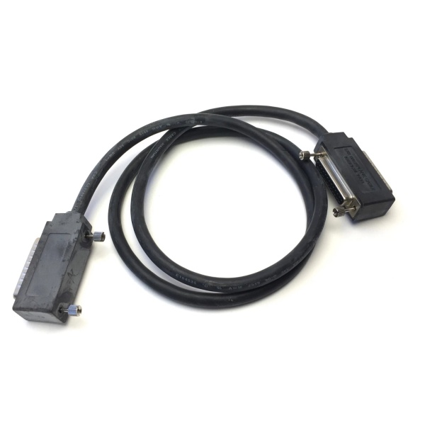
| Length | 10 feet (3 meters) |
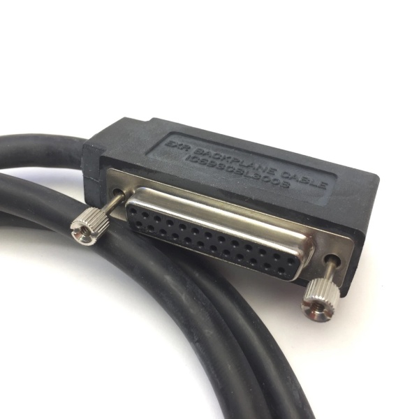
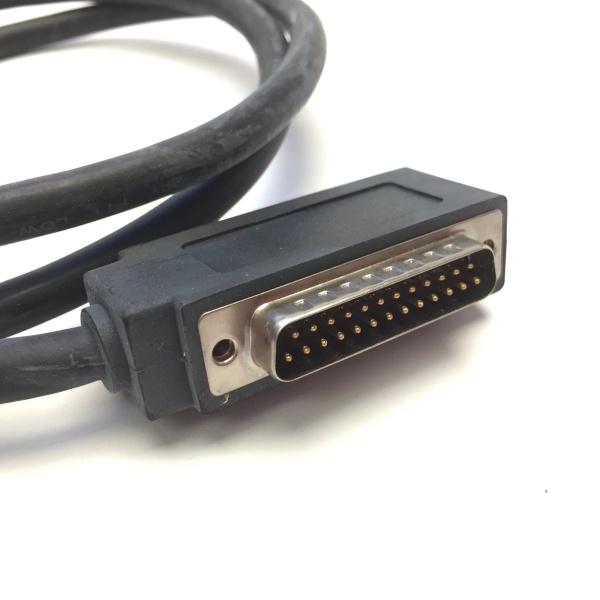
| Connector Type | Fujitsu FCN-365S024-AU (24-pin) |
| Connector Orientation | Right-Angle (90°) |
| Connector Depth | 2.0 inches (51 mm) from module front panel |
| Field Side Termination | Flying leads (stripped/tinned wires) |
| Wire Size | #24 AWG solid wire |
| Current Rating | 1.2 Amperes per conductor |
| Cable Configuration | 24 conductors, twisted pairs, color-coded |
| Shielding | Unshielded |
| Revision | Series C (Rev C) |
| Compatible Modules | IC693MDL654, IC693MDL655, IC693MDL752, IC693MDL753 |
| Complementary Cable | IC693CBL327 (Left Side, matching revision recommended) |
| Replaces | IC693CBL315 (when paired with IC693CBL327) |
| Product Lifecycle Status | Discontinued/Obsolete |
| Weight | 0.94 lbs (0.43 kg) |
IC693CBL300
4. Product Introduction
The GE IC693CBL328C is a high-density I/O interface cable designed for GE Fanuc Series 90-30 PLC systems. This cable is the Series C revision of the standard IC693CBL328 right-side cable, specifically engineered to connect 32-point high-density I/O modules to user-supplied terminal blocks or field wiring. The IC693CBL328C serves as the right-side cable in the pair and must be used in conjunction with the IC693CBL327 left-side cable (preferably with matching revision) to provide complete connectivity for dual-connector 32-point modules.
Featuring a Fujitsu FCN-365S024-AU 24-pin right-angle connector on the module end, this cable significantly reduces the clearance space required in front of the PLC cabinet compared to older straight-connector designs (IC693CBL315). The connector extends only 2.0 inches (51 mm) from the module’s front panel, making it ideal for space-constrained installations. The opposite end of the cable terminates in flying leads—stripped and tinned wires ready for connection to standard terminal blocks or PCB-based assemblies.
Constructed with 24 AWG twisted-pair conductors, each wire is color-coded for easy identification and rated for 1.2 amps per conductor. The cable is 3 meters (10 feet) in length, providing flexibility for field wiring routing. The IC693CBL328C, when paired with IC693CBL327, is compatible with Series 90-30 32-point modules including IC693MDL654, IC693MDL655, IC693MDL752, and IC693MDL753, as well as 16-point modules equipped with a TBQC I/O faceplate adapter. As a Series C revision, this cable may incorporate manufacturing improvements or component updates compared to earlier revisions (A and B).
5. QA & Testing SOP (Transparency Building)
1. Incoming InspectionVerify part number IC693CBL328C and confirm revision “C” against GE Fanuc records. Inspect the 24-pin Fujitsu FCN-365S024-AU connector for bent pins, corrosion, or housing damage. Confirm cable length is 3 meters. Check that flying leads are properly stripped and tinned (approximately 6mm exposed). Verify all 24 conductors are present and undamaged.
2. Visual InspectionExamine the right-angle connector orientation and ensure the connector housing is intact. Verify that the connector depth measurement (2.0 inches from mounting face) matches specifications. Check the cable jacket for cuts, abrasions, or heat damage. Inspect flying leads for correct color coding per the standard wire list (solid color + black tracer for each pair).
3. Pin-to-Wire Continuity TestingUsing a multimeter, verify continuity from each of the 24 connector pins to the corresponding flying lead. Confirm pin-to-wire mapping follows the standard configuration (pin 1 to wire 1, pin 2 to wire 2, etc.). Ensure there are no open circuits or miswired connections.
4. Insulation Resistance TestTest insulation resistance between adjacent conductors and between conductors and ground. Using a megohmmeter, verify insulation resistance exceeds 10MΩ to prevent short circuits during operation.
5. Conductor Current Rating VerificationConfirm wire gauge is #24 AWG solid wire and that each conductor can handle the 1.2 amp current rating. Verify that insulation rating is appropriate for the application voltage.
6. Connector Mating TestPerform a physical mating test with a compatible Series 90-30 I/O module to ensure proper connector alignment and locking mechanism engagement. Verify that the connector seats fully and that the right-angle orientation provides the expected 2-inch clearance depth.
7. Revision Compatibility CheckWhen pairing with IC693CBL327, verify that both cables have compatible revisions. While not strictly required to match revisions identically, using cables from the same revision family (e.g., both Series C) ensures consistent manufacturing characteristics. For replacement of IC693CBL315, both IC693CBL327C and IC693CBL328C are required.
8. Final QC & PackagingLabel with part number, revision (C), test date, and QC pass status. Package in anti-static bag with desiccant to prevent moisture damage during storage and transport.

IC693CBL300
6. Installation Pitfalls & Guide (Engineer to Engineer)
❗ Left/Right Cable PairingThe IC693CBL328C is the right-side cable and must be paired with the IC693CBL327 left-side cable for 32-point modules. A single cable (CBL328C only) provides only 24 pins and cannot fully support a 32-point module’s requirements. Using only one cable will result in incomplete connectivity.
❗ Revision CompatibilityWhen replacing cables, consider whether to match revisions. While revisions A, B, and C of IC693CBL327 and IC693CBL328 are electrically compatible, using cables from the same revision family (e.g., both Series C) ensures consistent manufacturing dates, connector quality, and potential material improvements.
❗ Cable Routing DirectionGE documentation specifies two routing configurations:
- Downward Routing: Connect IC693CBL327 to the LEFT connector and IC693CBL328C to the RIGHT connector.
- Upward Routing: Connect IC693CBL327 to the RIGHT connector and IC693CBL328C to the LEFT connector.Incorrect routing can cause cable crossing or interference in the cabinet.
❗ Connector Depth ConsiderationThe right-angle connector extends 2.0 inches (51 mm) from the module’s front panel. Ensure that the control cabinet provides sufficient depth to accommodate this extension. Insufficient clearance can damage the connector or cable when the cabinet door is closed, or cause accidental disconnection during maintenance.
❗ Flying Lead TerminationThe flying leads are stripped and tinned but require proper termination. Use ferrules (0.25mm² for 24AWG conductors) when connecting to terminal blocks to ensure secure connections and prevent stranded wire issues. Exposed strands can cause short circuits.
❗ Current Rating ViolationsEach conductor is rated for 1.2 amps maximum. When used with 16-point modules or in applications requiring higher current, calculate the per-point current draw carefully. Exceeding 1.2A per conductor causes conductor overheating and potential insulation failure.
❗ Cable Routing and Strain ReliefRoute cables away from sharp edges and high-voltage lines to prevent physical damage and electromagnetic interference. Secure cables to the enclosure using cable ties at least 100mm from the connector to prevent strain on the solder joints. Avoid bending cables within 50mm of connectors.
❗ TBQC Faceplate Adapter CompatibilityWhen used with 16-point modules equipped with a TBQC I/O faceplate adapter, ensure the connector orientation and pin mapping are compatible with the TBQC adapter specifications. Some TBQC applications require specific cable routing that affects which cable (CBL327 or CBL328C) connects to which side.
Installation Guide
-
Verify Compatibility: Confirm your I/O module is compatible (IC693MDL654/655/752/753) and that you have both the IC693CBL327 (left) and IC693CBL328C (right) cables for 32-point modules. Verify revision compatibility if desired.
-
Determine Routing Direction: Decide whether you need downward or upward cable routing based on your cabinet layout. This determines which cable connects to which connector.
-
Power Down: Ensure the PLC system and field power are de-energized before connecting cables.
-
Connect to Module:
- For Downward Routing: Connect IC693CBL327 to the LEFT connector and IC693CBL328C to the RIGHT connector.
- For Upward Routing: Connect IC693CBL327 to the RIGHT connector and IC693CBL328C to the LEFT connector.
- Align the right-angle connector with the appropriate port and insert firmly until fully seated and the locking mechanism engages. Verify the connector extends 2.0 inches from the module face.
-
Route Cables: Route the cables to your terminal block location, avoiding sharp edges and maintaining proper bend radius (minimum 10x cable diameter). Keep cables separated from AC power lines.
-
Terminate Flying Leads: Connect the flying leads to your terminal block according to the module’s wiring diagram. Use ferrules for stranded conductors to ensure reliable connections. Follow proper torque specifications for terminal screws.
-
Strain Relief: Secure cables to the enclosure using cable ties at approximately 150mm intervals, with the first tie at least 100mm from the connector.
-
Power Up and Verify: Restore power to the system. Verify I/O module status LEDs and check for proper signal continuity using PLC diagnostics or multimeter measurements.
7. FAQ (Frequently Asked Questions)
Q: What is the difference between IC693CBL328 and IC693CBL328C?A: IC693CBL328C is the Series C revision of the IC693CBL328 cable. The “C” suffix indicates a specific revision or manufacturing series. Electrically, all revisions (A, B, C) are compatible and have identical specifications (24-pin right-angle connector, 3m length, 1.2A rating). Series C may incorporate manufacturing improvements, material updates, or component changes compared to earlier revisions.
Q: Can I mix revisions (e.g., IC693CBL328C with IC693CBL327B)?A: Yes, revisions A, B, and C are electrically compatible and can be mixed. However, for consistency, using cables from the same revision family (e.g., both Series C) is recommended. This ensures matching manufacturing dates and potentially consistent connector quality.
Q: What is the difference between IC693CBL328C and IC693CBL327C?A: IC693CBL328C is the right-side cable, while IC693CBL327C is the left-side cable. Both have identical electrical specifications (24-pin right-angle connector, 3m length, 1.2A rating) but are designed to connect to the right and left ports of a 32-point I/O module, respectively. They are used as a pair for complete module connectivity.
Q: Can I use IC693CBL328C alone with a 32-point module?A: No, a 32-point module requires two 24-pin connectors (left and right) to accommodate all 32 I/O points. Using only IC693CBL328C provides connectivity for only half the module. You must use both CBL328C (or any revision) and CBL327.
Q: What modules are compatible with IC693CBL328C?A: IC693CBL328C is compatible with Series 90-30 32-point I/O modules including IC693MDL654, IC693MDL655, IC693MDL752, and IC693MDL753. It can also be used with 16-point modules equipped with a TBQC I/O faceplate adapter.
Q: What is the current rating per conductor?A: Each conductor in the IC693CBL328C cable is rated for 1.2 amps maximum. This rating must be considered when calculating load requirements for your I/O devices.
Q: Does this cable provide shielding?A: No, IC693CBL328C is an unshielded cable. If your application requires enhanced noise immunity, ensure proper installation practices (separation from power cables, use of shielded terminal blocks, etc.).
Q: Why does the connector have a right-angle design?A: The right-angle (90°) design reduces the clearance space required in front of the PLC cabinet. The connector extends only 2.0 inches from the module face compared to older straight-connector designs.
Q: How do I determine which cable connects to which side?A: According to GE documentation:
- Downward Routing: IC693CBL327 connects to the LEFT connector, IC693CBL328C connects to the RIGHT connector.
- Upward Routing: IC693CBL327 connects to the RIGHT connector, IC693CBL328C connects to the LEFT connector.The routing direction depends on your cabinet layout and cable management requirements.
Q: Can I build my own custom-length cable?A: Custom cables can be built, but only straight-connector kits (IC693CBL315) are available as individual components. Right-angle connector assemblies like CBL327C/CBL328C must be purchased as pre-manufactured cables. Refer to the “Building Custom Length Cables” section in the Series 90-30 installation manual for details.
Q: What is the connector depth rating?A: The IC693CBL328C connector extends 2.0 inches (51 mm) from the front panel of the I/O module. Ensure your control cabinet provides sufficient depth to accommodate this extension.
Q: Is IC693CBL328C the same as a programming cable?A: No, IC693CBL328C is an I/O interface cable for connecting I/O modules to field devices. It is not a programming cable. Programming cables for Series 90-30 use different connectors (e.g., RJ-12 to DB9) and communication protocols.
Q: Is there a cable kit that includes both IC693CBL327C and IC693CBL328C?A: The standard IC693CBK001 cable kit typically includes IC693CBL327 and IC693CBL328 (base revision). For matching Series C revisions, you may need to source IC693CBL327C and IC693CBL328C separately or inquire with suppliers about revision-specific kits.
Q: Are there alternative part numbers for IC693CBL328C?A: Alternative part numbers or common misspellings may include IC693CBL328/C, IC693C8L328, IC693CB1328. Always verify the correct part number and revision when ordering.


