
Description
Hard-Numbers: Technical Specifications
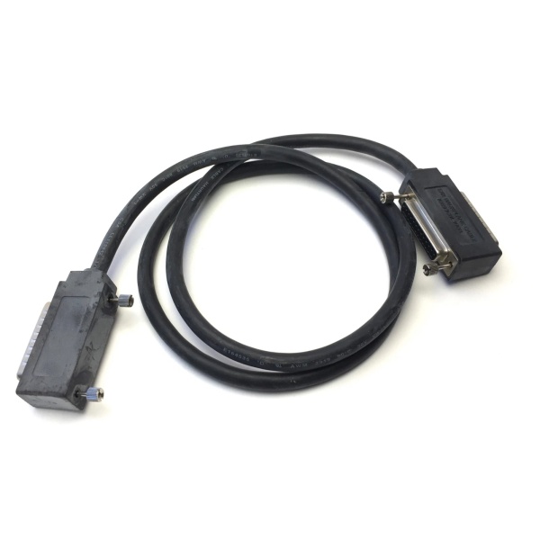
- Cable Type: High Density I/O Quick Connect Cable (Left Side)
- Cable Length: 3 meters (10 feet)
- Wire Size: #24 AWG (0.22 mm²)
- Current Rating: 1.2 Amperes per conductor
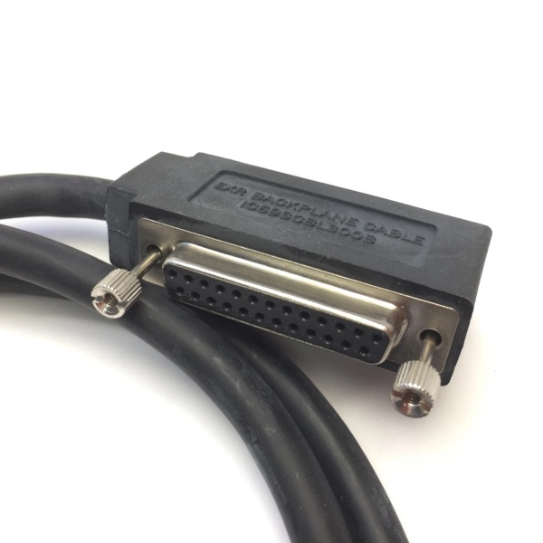
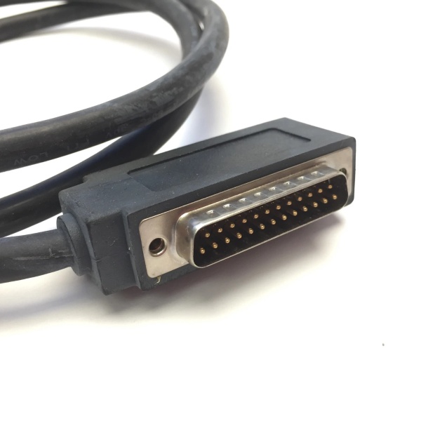
- PLC Side Connector: 24-pin right-angle female Fujitsu FCN-365S024-AU
- Field Side Connector: 24 flying leads (stripped and tinned)
- Connector Depth: 2.0 inches (51 mm) from module front panel
- Shield Type: Unshielded
- Wire Configuration: Twisted pairs with color coding
- Operating Temperature: Industrial range (typically -20°C to +70°C)
- Weight: 0.43 kg (0.94 lbs)
- Paired Cable Required: IC693CBL328 (right-side cable for groups A/B)
- Replaced Cable: IC693CBL315 (obsolete straight connector)
- Compatible Modules: IC693MDL654, IC693MDL655, IC693MDL752, IC693MDL753, IC694MDL752, IC694MDL753

GE IC693CBL300
The Real-World Problem It Solves
High-density 32-point I/O modules pack 32 discrete I/O points into a single card, but require two separate 24-pin connectors to break them out. Direct wiring to these Fujitsu connectors in tight cabinets eats up valuable working space and turns field changes into a nightmare of tracing individual pins through cramped conduit runs. The IC693CBL327C provides a prewired, right-angle solution that reduces front-panel clearance requirements and lets you land wires on a standard terminal block where you can actually see what you’re doing.
Where you’ll typically find it:
- 32-point output racks: Controlling solenoid banks, indicator arrays, or small motor starters where space is at a premium
- High-density input arrays: Sensor farms in packaging lines, conveyor systems, or assembly stations with dozens of limit switches and photoeyes
- Tight cabinet retrofits: Upgrading legacy panels where straight connector cables (IC693CBL315) won’t fit due to door interference or cable tray depth constraints
Bottom line: This cable buys you clearance space and wiring sanity when you’re working with 32-point modules—just remember you need the IC693CBL328 to complete the job.
Hardware Architecture & Under-the-Hood Logic
The IC693CBL327C is a passive interconnect cable—no active components, no magic inside, just copper and insulation. Its job is straightforward: bridge the gap between the module’s left-side 24-pin Fujitsu connector (groups C and D, points 17-32) and your field termination point without adding impedance, voltage drop, or points of failure.
-
Signal Path FlowThe cable carries 24 discrete signal paths plus common returns directly from the module’s connector pins to your terminal block. Each pin maps 1:1 to a flying lead—pin 1 becomes wire 1, pin 2 becomes wire 2, no cross-wiring, no surprises. Signals travel unbroken from the module backplane through the Fujitsu connector, down 3 meters of #24 AWG copper, and land at your field terminals.
-
Connector Design LogicThe right-angle Fujitsu FCN-365S024-AU connector mates to the module’s male header and bends 90 degrees immediately, routing the cable downward or parallel to the panel instead of sticking straight out like the obsolete IC693CBL315. This shaves precious inches off the front-panel protrusion—critical when your cabinet door is trying to close over a dense I/O rack. The connector shell is plastic, the contacts are phosphor bronze, and the whole assembly only extends 2 inches from the module face.
-
Current Capacity & Wire Gauge Reality#24 AWG copper handles 1.2 amps per conductor max—period. That’s your hard ceiling regardless of what the module or field device spec sheet says. If you’re driving 16-point outputs rated for 2 amps each, this cable derates your entire bank to 1.2 amps per point. The physics don’t negotiate. Running 1.5 amps through a #24 conductor heats the wire, melts insulation over time, and eventually leaves you with a short circuit or open conductor inside the cable jacket where you can’t fix it.
-
Left-Side Group AssignmentOn 32-point modules, the left-side connector handles groups C and D (points 17-32). Group C is typically points 17-24, Group D is points 25-32. Each group of 8 shares a common return. The IC693CBL327C doesn’t know or care about this grouping—it just passes through whatever voltage or signal the module puts on each pin. Your terminal block wiring determines how you actually land the commons and field devices.
-
Unshielded Trade-OffThis cable has no foil or braid shielding. It relies entirely on twisted pairs for noise rejection, which works fine for typical 24VDC I/O in reasonably clean environments. But run it past a VFD output cable, sit it next to a 480V power bus, or route it through a conduit with welding leads, and you’ll pick up noise that manifests as ghost inputs or erratic outputs. Shielding costs money and adds stiffness—GE cut it to keep this cable flexible and cheap.
-
Flying Lead Termination StrategyThe field end gives you 24 loose wires with stripped and tinned ends. You can land these directly into screw terminals, ferrule lugs, or even solder them to a custom PCB if that’s your thing. No pre-molded connector means maximum flexibility but also maximum responsibility—you need to label each wire clearly, verify continuity after termination, and secure the bundle so strain doesn’t pull your terminals loose during vibration events.
GE IC693CBL300
Field Service Pitfalls: What Rookies Get Wrong
Mixing left and right cables
You install the IC693CBL327C on the right-side connector or swap left and right positions when you’re tired and rushing. The module still powers up, but points 1-16 are completely dead while points 17-32 work fine—or vice versa. You waste hours troubleshooting the module, power supply, and field devices before realizing you swapped the cables.
- Field Rule: Label left and right cables clearly during installation. IC693CBL327 (Left) always goes to the left-side connector for groups C/D (points 17-32). IC693CBL328 (Right) always goes to right-side for groups A/B (points 1-16). Never guess—look at the module silkscreen or verify pinout against the manual before plugging in.
Forgetting the paired cable
You order and install only the IC693CBL327C, thinking one cable handles the whole 32-point module. Half your I/O points are dead on arrival. The module shows green, the left cable is perfect, but nothing connected to the right-side connector works because there’s no cable there.
- Field Rule: 32-point modules require both cables—period. IC693CBL327 (Left) plus IC693CBL328 (Right) equals one complete module hookup. Order them as a pair, stock them as a pair, and install them as a pair. Missing either cable leaves you with 50% capacity.
Exceeding 1.2 amp current limit
You wire a 16-point output module through this cable and load each point to 2 amps because the module spec says it’s good for that much. The #24 AWG conductors overheat, insulation degrades, and within months you’re tracking down intermittent faults or outright conductor failures.
- Field Rule: 1.2 amps per conductor is your absolute maximum, regardless of module rating. For 16-point modules with higher current capabilities, you must use the lower cable rating or switch to a different wiring method. Verify field device currents during design, not after the smoke clears.
Ignoring connector depth in tight cabinets
You mount modules close to the cabinet door without accounting for the 2-inch connector protrusion. The door won’t close, you force it, and you crush the right-angle shell or crack the connector housing. Now you’re hunting for a replacement cable at 2 AM.
- Field Rule: Measure 2 inches minimum from module face to any obstruction before mounting. Account for cable bend radius too—these right-angle connectors need room to turn downward. If the cabinet’s too shallow, consider relocating modules or using a deeper enclosure.
Poor flying lead termination
You strip wires too short, nick conductors with strippers, or leave loose strands in terminal blocks. Six months later, vibration works the connections loose, and you’re chasing phantom faults that come and go with machine operation.
- Field Rule: Strip 6-8 mm, never nick the copper, use ferrules if your terminal blocks accept them. Torque to spec, not hand-tight. Pull-test each termination after crimping or screwing down. A 5-minute termination job done right beats 5 hours of fault-finding on a running line.
Hot-swapping cables under load
You plug or unplug this cable while field power is applied to the I/O points. Outputs fire unexpectedly, inputs glitch, and worst case—you activate machinery that shouldn’t be running. Someone gets hurt, or product gets wasted.
- Field Rule: Kill field power before touching I/O cables. Verify zero volts with a multimeter. Follow proper lockout/tagout. Never assume “it’s just a cable”—those flying leads carry live voltage to field devices, and accidental energization kills productivity and people.
Using unshielded cable in high-EMI environments
You run IC693CBL327C past VFD outputs, motor starters, or welding equipment without additional protection. Electrical noise induces false inputs or erratic outputs that you blame on the module, program, or field devices.
- Field Rule: Understand this cable is unshielded. Keep it separated from power cables by at least 12 inches. Route through steel conduit if you’re in high-EMI areas. If noise immunity is critical, consider shielded alternatives or re-route cable paths. Noise faults are hell to troubleshoot—prevent them during installation.
Damaging connectors during installation
You force the Fujitsu connector onto misaligned pins, or you pull cables by the connector body instead of the wire bundle. Pins bend, shells crack, and contact plating wears off. Intermittent connections become your new normal.
- Field Rule: Connectors must slide on smoothly—never force. Align carefully, push straight on until it clicks. Pull by the wire bundle, never the connector. Inspect pins for damage before installation. Once you crack that connector shell, you’re buying a new cable—there’s no field fix.
Incorrect wire mapping assumptions
You assume wire color coding matches your terminal block layout without verifying the pinout. Points activate in the wrong order, or worse—you short commons to outputs when you land them based on assumption instead of documentation.
- Field Rule: Never assume wire mapping. Verify pin 1 connects to wire 1, pin 2 to wire 2. Use a continuity tester if labels are missing. Cross-check against the module manual and your terminal block diagram. One wrong wire kills a board or starts a fire.
Commercial Availability & Pricing Note
Please note: The listed price is for reference only and is not binding. Final pricing and terms are subject to negotiation based on current market conditions and availability.


