
Description
Hard-Numbers: Technical Specifications
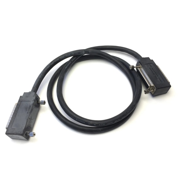
- Cable Type: High Density I/O Quick Connect Cable (Left Cable)
- Cable Length: 3 meters (10 feet)
- Cable Construction: Unshielded twisted-pair cable
- Wire Size: #24 AWG (0.22 mm²)
- Current Rating: 1.2 Amperes per conductor
- Temperature Rating: Industrial environment (typically -20°C to +70°C)
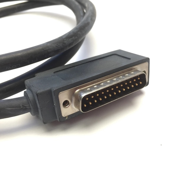
- PLC Side Connector: 24-pin right-angle female Fujitsu connector (FCN-365S024-AU)
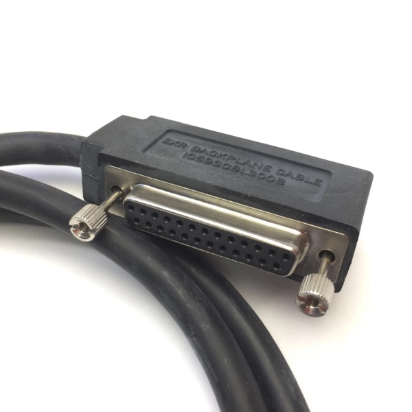
- Field Side Connector: Flying leads (24 stripped and tinned wires)
- Connector Depth: 2 inches (51 mm) from module front panel
- Connector Orientation: Right-angle (90-degree) design
- Shield Type: Unshielded
- Weight: 0.43 kg (0.94 lbs)
- Shipping Weight: 2.0 kg (4.4 lbs)
- Compatible I/O Modules: IC693MDL654, IC693MDL655, IC693MDL752, IC693MDL753, IC694MDL752, IC694MDL753
- Paired Cable: IC693CBL328 (required for right-side connector, groups A and B)
- Replaced Cable: IC693CBL315 (obsolete straight connector design)
- TBQC Compatibility: Yes – works with TBQC I/O faceplate adapters
- Wire Configuration: Pin-to-wire continuity (pin 1 connects to wire 1)
- Wire Color Coding: Twisted pairs with color-coded identification
- Lifecycle Status: Discontinued/Obsolete

GE IC693CBL300
The Real-World Problem It Solves
Standard 32-point high-density I/O modules on Series 90-30 PLCs require two separate 24-pin connectors to interface with all I/O points. Direct wiring to these Fujitsu connectors is time-consuming and error-prone in tight cabinet spaces. The IC693CBL327 provides a prewired, right-angle quick-connect solution that simplifies field wiring while reducing clearance space requirements. When paired with IC693CBL328, it enables rapid, organized connection of all 32 I/O points to user-supplied terminal blocks, significantly reducing installation time and wiring errors.
Where you’ll typically find it:
- High-density I/O installations: Wiring 32-point input or output modules (IC693MDL654, IC693MDL655, IC693MDL752, IC693MDL753) to field devices
- Tight cabinet applications: Right-angle connector design minimizes clearance space in crowded control cabinets
- TBQC terminal block systems: Connecting modules to DIN-rail mounted TBQC interposing terminal blocks
- Direct field wiring: Flying leads enable connection to user-supplied PCB-based terminal blocks or standard terminal assemblies
- 16-point module retrofits: Used with TBQC I/O faceplate adapters for simplified wiring on 16-point modules
Bottom line: The IC693CBL327 simplifies high-density I/O wiring with its right-angle design and flying leads, enabling fast, organized field connections while working in pairs with IC693CBL328 for complete 32-point module coverage.
Hardware Architecture & Under-the-Hood Logic
The IC693CBL327 is a prewired I/O interface cable designed specifically for Series 90-30 high-density I/O modules. Its right-angle connector orientation and flying-lead field end provide flexibility for various wiring configurations while reducing cabinet clearance requirements.
-
Cable Construction
- Unshielded twisted-pair cable (no EMI shielding)
- #24 AWG conductors with 1.2 amp current rating per wire
- Twisted pairs for noise immunity on signal lines
- Color-coded wires for easy identification
- Pin-to-wire continuity (pin 1 connects to wire 1, pin 2 to wire 2, etc.)
- Total of 24 individual conductors
-
Connector Configuration
- PLC End (Module Side): 24-pin right-angle female Fujitsu connector
- Connector type: Fujitsu FCN-365S024-AU
- Orientation: Right-angle (90-degree bend from module face)
- Depth: 2.0 inches (51 mm) from module front panel
- Mates with male 24-pin connectors on high-density I/O modules
- Field End: 24 flying leads (stripped and tinned wires)
- Can be connected to user-supplied terminal blocks
- Compatible with PCB-based terminal assemblies
- Supports standard terminal block connections
- Left-Side Design: Specifically designed for left-side connector on 32-point modules
- Interfaces with I/O groups C and D
- Requires IC693CBL328 for right-side connector (groups A and B)
- PLC End (Module Side): 24-pin right-angle female Fujitsu connector
-
Module Interface GroupsFor 32-point high-density I/O modules:
- Right-side connector (IC693CBL328): Handles groups A and B (points 1-16)
- Left-side connector (IC693CBL327): Handles groups C and D (points 17-32)
- Each group of 8 points shares a common connection
- Isolated groups provide flexibility in wiring configurations
-
Current Rating Constraints
- Maximum 1.2 Amperes per conductor
- If using with 16-point output modules rated higher than 1.2 amps:
- Must use the lower 1.2 amp limit
- For field devices requiring more than 1.2 amps:
- Do not use TBQC assembly
- Use standard terminal board instead
- Total module current limits still apply per module specifications
-
TBQC Terminal Block System Integration
- Connects from module connectors to DIN-rail mounted TBQC terminal blocks
- TBQC components provide organized, labeled termination points
- Reduces wiring errors and simplifies maintenance
- Alternative to direct field wiring with flying leads
-
Right-Angle Advantage
- Reduces clearance space required in front of PLC
- Cables can be routed downward or upward from module
- Provides more working space than obsolete IC693CBL315 (straight connector)
- Ideal for tight cabinet installations
-
Cable Pairing Logic
- IC693CBL327 (Left): Groups C and D, points 17-32
- IC693CBL328 (Right): Groups A and B, points 1-16
- Both cables required for complete 32-point module wiring
- Both cables share identical specifications and connector depth
-
16-Point Module Compatibility
- Can be used with 16-point I/O modules
- Requires TBQC I/O faceplate adapter
- Simplifies wiring on modules with single connector
- Flying leads provide flexible termination options
GE IC693CBL300
Field Service Pitfalls: What Rookies Get Wrong
Using wrong cable for connector side
Rookies install IC693CBL327 on the right-side connector instead of left-side. I/O points 1-16 (groups A and B) are not connected, causing missing field device connections.
- Field Rule: Always verify connector orientation. IC693CBL327 (Left Cable) goes to left-side connector for groups C and D (points 17-32). IC693CBL328 (Right Cable) goes to right-side connector for groups A and B (points 1-16). Label cables clearly during installation to prevent mix-ups.
Exceeding 1.2 amp current limit
Rookies connect high-current loads exceeding 1.2 amps to individual conductors. Conductors overheat, insulation melts, and potential fire hazard occurs.
- Field Rule: Never exceed 1.2 amp current rating per conductor. Verify load currents for all field devices before connection. For 16-point output modules with higher ratings, you must derate to the 1.2 amp limit. If devices require more than 1.2 amps, use standard terminal board instead of TBQC assembly.
Forgetting to install paired cable
Rookies only install IC693CBL327 and omit IC693CBL328 on 32-point modules. Only points 17-32 function, while points 1-16 are completely dead.
- Field Rule: Always install both IC693CBL327 and IC693CBL328 on 32-point high-density I/O modules. Verify both connectors are populated and cables are securely seated. Document cable installation in as-built drawings. Missing either cable will result in 50% of I/O points being non-functional.
Connecting flying leads without proper termination
Rookies strip wires incorrectly or fail to properly terminate flying leads in terminal blocks. Loose connections cause intermittent operation, voltage drops, or complete circuit failures.
- Field Rule: Strip flying leads to proper length (typically 6-8 mm) without nicking conductors. Tighten terminal blocks to specified torque. Verify continuity from module connector to field device after termination. Use ferrules if specified by terminal block manufacturer. Poor termination is the #1 cause of I/O system failures.
Ignoring connector depth requirements
Rookies mount PLC modules too close to cabinet door, ignoring 2-inch connector depth. Cabinet door won’t close, or cables are crushed, damaging connectors and conductors.
- Field Rule: Ensure minimum 2.0-inch (51 mm) clearance from module front panel to any obstruction. Measure cabinet depth before mounting modules. Account for right-angle connector protrusion. For tight cabinets, consider relocating modules or using cabinets with adequate depth. Never force cables to fit insufficient clearance.
Mixing old and new cable designs
Rookies pair IC693CBL327 with obsolete IC693CBL315 straight connector. Cables don’t match orientation, causing cable stress and potential connector damage.
- Field Rule: Always use matching cable pairs. IC693CBL327 and IC693CBL328 are designed as a matched set with identical right-angle connectors. Do not mix with obsolete IC693CBL315. When upgrading from old cables, replace both IC693CBL327 and IC693CBL328 together to ensure proper fit and orientation.
Using in electrically noisy environments
Rookies deploy unshielded IC693CBL327 in high-EMI environments without additional protection. Electrical noise causes intermittent I/O faults and unpredictable system behavior.
- Field Rule: Understand that IC693CBL327 is unshielded. Avoid use in areas with VFDs, welding equipment, or strong RF sources. If noise immunity is critical, consider shielded alternatives or route cables away from noise sources. Use proper cable separation distances (minimum 12 inches) from power cables. Noise-induced faults are difficult to diagnose—prevent them during installation.
Improper wire color coding identification
Rookies ignore color-coded twisted pairs and wire conductors incorrectly. Wrong devices activate, safety systems fail, or system operation becomes unpredictable.
- Field Rule: Always follow color-coded wire identification carefully. Document wire mapping from module pins to field devices. Verify each connection before energizing. Use continuity tester to confirm pin-to-wire relationships. Never assume wire color mapping—always verify against module documentation. Incorrect wiring can cause safety hazards and equipment damage.
Hot-swapping cables with power applied
Rookies connect or disconnect IC693CBL327 while field power is applied. Field devices activate unexpectedly, causing uncontrolled machine motion or equipment damage.
- Field Rule: Always disconnect field power before connecting or disconnecting I/O cables. Verify power is off using a multimeter. Follow proper lockout/tagout procedures. Never hot-swap I/O connections under load. Unexpected activation of outputs can cause serious injury or equipment damage.
Damaging connectors during installation
Rookies force connectors onto module pins or pull cables by the connector body. Pins bend, connector shells crack, and cable integrity is compromised.
- Field Rule: Connectors must mate smoothly—never force. Align connectors carefully before pushing onto module pins. Pull cables by the wire bundle, not the connector body. Inspect pins for damage before installation. Damaged connectors cannot be repaired—cable must be replaced. Handle connectors with care to avoid costly replacements.
Using with incompatible I/O modules
Rookies attempt to use IC693CBL327 with standard 24-pin I/O modules that don’t have Fujitsu connectors. Cables don’t fit, wasting time and causing installation delays.
- Field Rule: Verify I/O module compatibility before ordering IC693CBL327. This cable is only for high-density I/O modules with Fujitsu 24-pin connectors (IC693MDL654, IC693MDL655, IC693MDL752, IC693MDL753, and their IC694 equivalents). Standard 24-pin I/O modules use different wiring methods. Always confirm module型号 and connector type before installation.
Commercial Availability & Pricing Note
Please note: The listed price is for reference only and is not binding. Final pricing and terms are subject to negotiation based on current market conditions and availability.


