
Description
Hard-Numbers: Technical Specifications
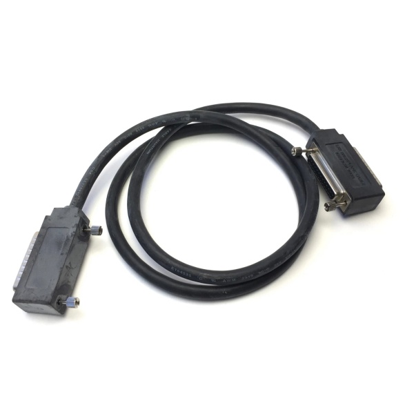
- Cable Type: I/O Bus Expansion Cable (Wye Cable)
- Cable Length: 1 meter (3 feet)
- Cable Construction: Belden 8107 twisted-pair, 24 AWG (0.22 mm²) tinned copper
- Cable Shielding: Continuous braid over foil shield (100% shield coverage)
- Voltage Rating: 30 VDC
- Temperature Rating: 80°C (176°F)
- Nominal Impedance: 100Ω
- Velocity of Propagation: 70%
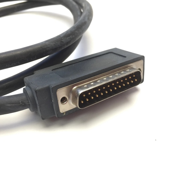
- Connector 1 (End A): 25-pin male D-Sub connector
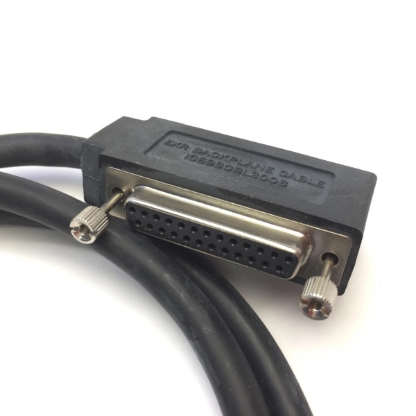
- Connector 2 (End B): Dual 25-pin D-Sub connector (one male, one female)
- Weight: 0.25 lbs (0.11 kg)
- Insulation Resistance: 10 MΩ
- Voltage Withstand: 2,000 V
- Maximum Expansion Cables: 7 (CPUs 350-364), 4 (CPUs 331-341)
- Maximum Expansion Length: 15 meters (50 feet) total from CPU to last expansion baseplate
- Maximum Remote Length: 213 meters (700 feet) total from CPU to last remote baseplate
- Termination Required: Yes – IC693ACC307 Terminator Plug or built-in termination (IC693CBL302/314)
- Compatible Systems: Series 90-30, PACSystems RX3i (with Serial Bus Transmitter Module)
- Product Lifecycle Status: Discontinued/Obsolete

GE IC693CBL300
The Real-World Problem It Solves
Standard PLC backplanes have limited I/O slot capacity. When applications require more I/O points than a single CPU baseplate can accommodate, expansion racks are needed. The IC693CBL300 provides the critical bus extension link between the CPU and expansion/remote baseplates, enabling system scalability while maintaining reliable high-speed I/O communication over shielded twisted-pair cabling.
Where you’ll typically find it:
- Cabinet expansion: Connecting CPU rack to additional expansion racks within the same control cabinet
- Remote I/O distribution: Extending I/O bus to remote baseplates located up to 700 feet from CPU
- System upgrades: Adding I/O capacity to existing Series 90-30 installations without CPU replacement
- Custom cable assemblies: Used as Wye jumper adapter for building custom-length point-to-point cables when standard lengths don’t fit
Bottom line: The IC693CBL300 enables flexible I/O bus expansion for Series 90-30 systems, supporting both local expansion (up to 50 feet) and remote I/O distribution (up to 700 feet) while providing daisy-chain capability for multi-rack configurations.
Hardware Architecture & Under-the-Hood Logic
The IC693CBL300 is a prewired I/O bus expansion cable designed to extend the Series 90-30 I/O bus from the CPU baseplate to expansion or remote baseplates. Its Wye connector design allows daisy-chaining multiple expansion racks, creating a scalable I/O system architecture.
-
Cable Construction
- Belden 8107 twisted-pair cable (no substitutes approved)
- 24 AWG (0.22 mm²) tinned copper conductors with 7×32 stranding
- Continuous braid over foil shielding for maximum EMI protection
- 30 VDC voltage rating, 80°C temperature rating
- 100Ω nominal impedance, 70% velocity of propagation
- Shield must be continuous across entire cable length, including at terminations
-
Connector Configuration
- End A (Single connector): 25-pin male D-Sub connector – connects to CPU baseplate
- End B (Dual connector): Two-headed 25-pin D-Sub connector
- Male connector: connects to first expansion baseplate
- Female connector: accepts next cable in daisy-chain or termination plug
- All connectors use standard DB25 pinout for I/O bus signals
-
Signal Pair ConfigurationThe I/O bus uses differential signal pairs for noise immunity:
- Pins 2-3: DFRAME/ (Cycle Frame)
- Pins 8-9: DRMRUN/ (Remote Run)
- Pins 12-13: DRPERR/ (Parity Error)
- Pins 16-17: DATA/ (I/O Serial Data)
- Pins 20-21: DRSEL/ (Remote Select)
- Pins 24-25: DIOCLK/ (I/O Serial Clock)
- Pin 1: Shield drain wire (ground connection)
-
Termination Requirements
- Each signal pair requires 120Ω, 1/4W termination resistor at bus end
- Termination options:
- IC693ACC307 Terminator Plug on last expansion baseplate
- IC693CBL302/314 (15m cable with built-in termination)
- Custom cable with termination resistors in end connector
- For factory-made Wye cables like IC693CBL300, Pin 1 must be broken out at the male end where it plugs into the remote rack
-
Daisy-Chain Architecture
- Single male connector plugs into CPU baseplate
- Dual-connector end provides connection to first expansion rack and daisy-chain continuation
- Female connector accepts either next expansion cable or termination plug
- Supports up to 7 expansion racks (CPUs 350-364) or 4 racks (CPUs 331-341)
-
Custom Cable Applications
- IC693CBL300 serves as Wye jumper adapter for custom point-to-point cables
- Point-to-point cables (single male-to-female connectors) are easier to fabricate than Wye cables
- This combination saves time when custom lengths are required
- Essential when routing through conduits too small for standard Wye connectors
GE IC693CBL300
Field Service Pitfalls: What Rookies Get Wrong
Connecting cables with power applied
Rookies plug or unplug IC693CBL300 while the expansion baseplate has power. Unexpected PLC operation occurs, potentially damaging modules or causing uncontrolled machine motion.
- Field Rule: Always disconnect power from expansion/remote baseplates before connecting or disconnecting I/O bus expansion cables. Verify power is off using a multimeter before touching connectors. Never hot-swap expansion cables.
Exceeding cable length limits
Rookies chain multiple cables beyond 15 meters for expansion or 700 feet for remote I/O. Signal degradation causes erratic PLC operation, intermittent I/O faults, or complete communication failure.
- Field Rule: Never exceed 15 meters (50 feet) total length between CPU and last expansion baseplate. For remote baseplates, maximum is 213 meters (700 feet). Measure and document total cable length during installation. Use Serial Bus Transmitter Module (IC695LRE001) for RX3i systems to maintain proper signal integrity.
Improper bus termination
Rookies forget to install the termination plug or resistors at the last rack. Signal reflections cause data errors, especially at higher speeds, leading to unpredictable system behavior.
- Field Rule: Always terminate the I/O bus at the last expansion or remote baseplate. Use IC693ACC307 Terminator Plug, IC693CBL302/314 (15m cable with built-in termination), or install 120Ω resistors between signal pairs (pins 2-3, 8-9, 12-13, 16-17, 20-21, 24-25). Never leave the bus unterminated.
Using wrong cable type
Rookies substitute Belden 8107 with generic shielded cable. Impedance mismatch and inadequate shielding cause communication failures in electrically noisy environments.
- Field Rule: Use only Belden 8107 cable (or exact equivalent) for building custom I/O bus expansion cables. Do not substitute. The 100Ω nominal impedance and 70% velocity of propagation are critical for signal integrity. Verify cable markings before installation.
Grounding shield incorrectly
Rookies ground the cable shield at both ends, creating ground loops. Noise immunity is compromised, causing intermittent communication errors that are difficult to diagnose.
- Field Rule: Ground the cable shield at one end only (typically the CPU baseplate end). For factory-made Wye cables like IC693CBL300, Pin 1 is broken out at the male end that plugs into the remote rack. Ensure shield continuity across all connections without creating multiple ground paths.
Exceeding CPU expansion limits
Rookies install 8 expansion racks with a CPU 350. The 8th rack is ignored, causing missing I/O points and unpredictable system behavior.
- Field Rule: Respect CPU expansion limits. CPUs 350-364 support maximum 7 expansion cables (7 racks). CPUs 331-341 support maximum 4 expansion cables (4 racks). Document rack count and CPU model in as-built drawings. If more racks are needed, consider additional CPUs or remote I/O distribution.
Daisy-chaining incorrectly
Rookies plug cables in wrong order or skip expansion racks in the chain. Bus communication fails, and downstream racks don’t respond.
- Field Rule: Install cables in correct daisy-chain order. Single male connector → CPU baseplate. Dual-connector end male → first expansion rack. Dual-connector end female → next cable or termination. Verify each connection clicks securely and document rack numbering sequence.
Ignoring cable bend radius
Rookies make sharp bends near connectors to fit tight spaces. Internal conductors are damaged, causing intermittent connections or open circuits that are difficult to trace.
- Field Rule: Maintain minimum bend radius (typically 10x cable diameter) when routing cables. Use cable management systems to support cables and prevent sharp bends. Never force cables into tight spaces—re-route to accommodate proper bend radius. Damaged conductors from sharp bends cannot be repaired—cable must be replaced.
Mixing expansion and remote I/O incorrectly
Rookies attempt to use IC693CBL300 beyond specified distance limits. Signal integrity is compromised, causing communication failures that are attributed to other issues.
- Field Rule: Understand the difference between expansion and remote I/O. Expansion baseplates: maximum 15 meters (50 feet) from CPU. Remote baseplates: maximum 213 meters (700 feet) from CPU. Use appropriate cable types and verify total length. For distances approaching limits, consider Serial Bus Transmitter Module or fiber optic solutions.
Commercial Availability & Pricing Note
Please note: The listed price is for reference only and is not binding. Final pricing and terms are subject to negotiation based on current market conditions and availability.


