
Description
3. Key Technical Specifications
| Parameter | Value |
|---|---|
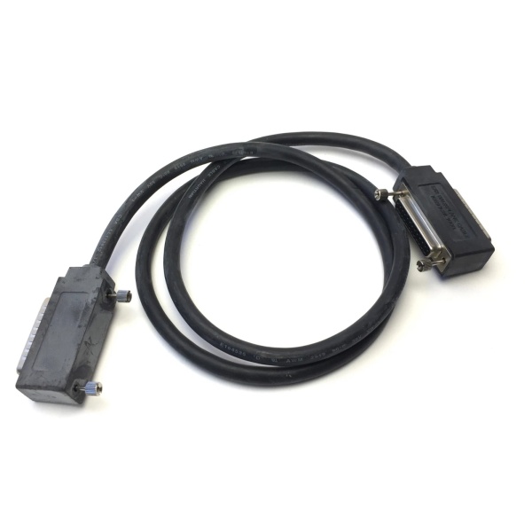
| Type | I/O Bus Expansion Cable (Wye Cable) |
| Length | 3 feet (1 meter) |
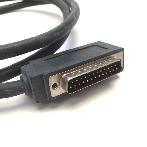
| Connector 1 (End 1) | Single 25-Pin D-Sub Male Connector |
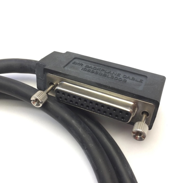
| Connector 2 (End 2) | Dual-Head 25-Pin D-Sub Connectors (1 Male, 1 Female) |
| Cable Type | Belden 8107 (Twisted Pair, 24 AWG) |
| Shielding | 100% Continuous Shield (Braid over Foil) |
| Impedance | 100Ω Nominal |
| Voltage Rating | 30V DC |
| Current Rating | 24 AWG Copper |
| Compatibility | Series 90-30 Baseplates, RX3i Serial Expansion Backplanes |
| Maximum System Length | 50 ft (15 m) total for expansion; 700 ft (213 m) for remote |
| Maximum Cables in Chain | 7 (CPUs 350-364) or 4 (CPUs 331-341) |
| Product Lifecycle Status | Discontinued/Obsolete |
| Weight | 0.25 lbs (0.11 kg) |
IC693CBL300
4. Product Introduction
The GE IC693CBL300 is an I/O Bus Expansion Cable, commonly referred to as a “Wye cable,” designed for GE Fanuc Series 90-30 PLC systems and PACSystems RX3i Serial Expansion Backplanes. This cable extends the I/O bus from the CPU baseplate to expansion or remote baseplates, enabling system scalability when additional I/O slots are required or when baseplates need to be positioned at a distance from the CPU.
The cable features a unique three-connector configuration: one end has a single 25-pin D-sub male connector, while the other end has a dual-head 25-pin D-sub connector (one male and one female). This Wye configuration supports daisy-chaining, allowing up to seven expansion baseplanes to be linked in a single system. The cable is 1 meter (3 feet) in length and constructed with Belden 8107 twisted-pair wire with 100% continuous shielding (braid over foil) to ensure noise immunity and signal integrity in industrial environments.
In addition to standard expansion applications, the IC693CBL300 can serve as a Wye jumper adapter for building custom-length point-to-point cables, simplifying the assembly of custom wiring solutions.
5. QA & Testing SOP (Transparency Building)
1. Incoming InspectionVerify part number and revision (e.g., IC693CBL300, IC693CBL300A) against GE Fanuc records. Inspect all three 25-pin D-sub connectors for bent pins, corrosion, or damage to the metal shells. Confirm cable length is 1 meter (3 feet). Check the continuous shielding for cuts or abrasions that could compromise noise immunity.
2. Visual InspectionInspect the dual-head connector end to ensure both the male and female connectors are present and properly aligned. Verify that the metal connector shells make proper contact with the cable shield for grounding. Check cable jacket integrity and connector strain relief for signs of damage or wear.
3. Electrical Continuity TestingUse a multimeter to verify continuity for all 25 pins between the single male connector end and both the male and female connectors on the dual-head end. Confirm that pin 1 connections align with the specific baseplate requirements (some older remote baseplates require pin 1 to be removed or not connected).
4. Shield Integrity TestMeasure the continuity of the shield across the entire cable length. Verify that the drain wire or shield makes proper contact with the metal connector shells at both ends. Ensure there are no breaks in the 100% continuous shielding.
5. Insulation Resistance TestUsing a megohmmeter, test insulation resistance between adjacent conductors and between conductors and the shield. The insulation resistance should exceed 10MΩ to prevent short circuits and ensure reliable signal transmission.
6. Compatibility VerificationTest cable fit with compatible Series 90-30 baseplates (IC693CHS391/392/393/397/398/399) or RX3i Serial Expansion Backplanes (IC694/693CHS392/398). Verify proper mating and locking of connectors.
7. Final QC & PackagingLabel with part number, test date, and QC pass status. Package in anti-static bag with desiccant to prevent moisture damage during storage and transport.

IC693CBL300
6. Installation Pitfalls & Guide (Engineer to Engineer)
❗ Daisy-Chain OrientationThe Wye cable must be installed with correct orientation. Connect the single male connector to the CPU baseplate (or previous expansion baseplate). Connect the male connector from the dual-head end to the next expansion baseplate. The female connector on the dual-head end is reserved for either the next cable in the chain or the terminator plug.
❗ Pin 1 Requirements for Older BaseplatesFor early remote baseplates (IC693CHS393E and earlier, IC693CHS399D and earlier), pin 1 on the cable connector mating to the baseplate must be removed or the shield drain wire must not be connected. Failure to do so can cause grounding issues. Newer baseplate revisions do not require this modification.
❗ Exceeding Maximum Cable LengthThe total maximum cable length from the CPU baseplate to the last expansion baseplate is 50 feet (15 meters). The total maximum distance to the last remote baseplate is 700 feet (213 meters). Exceeding these limits can cause erratic PLC operation, signal degradation, or communication failures.
❗ Improper TerminationThe last baseplate in the expansion chain must be properly terminated. This can be achieved using an I/O Bus Terminator Plug (IC693ACC307), by using the 50-foot cable (IC693CBL302/314) with built-in terminating resistors, or by building a custom cable with 120Ω termination resistors on the appropriate signal pairs (pins 2-3, 8-9, 12-13, 16-17, 20-21, 24-25). Failure to terminate will cause signal reflections and system instability.
❗ Connecting/Disconnecting Under PowerNever connect or disconnect I/O Bus Expansion cables while power is applied to the I/O expansion baseplates. This can cause unexpected PLC operation, data corruption, or hardware damage. Always power down the system before making or breaking connections.
❗ Shielding GroundingThe cable’s 100% continuous shield must be properly grounded through the metal connector shells. Ensure that connector shells are fully seated and making metal-to-metal contact with the baseplate connectors to maintain shield continuity. Improper grounding reduces noise immunity.
Installation Guide
-
System Planning: Determine the number of expansion/remote baseplates and calculate total cable length. Ensure total length does not exceed 15 meters (expansion) or 213 meters (remote). Verify CPU model supports the required number of expansion cables (4 or 7).
-
Power Down: Turn off power to all baseplates in the system.
-
First Connection: Connect the single male connector of the IC693CBL300 to the 25-pin female connector on the CPU baseplate (or the previous expansion baseplate in a daisy-chain).
-
Chain Connection: Connect the male connector from the dual-head end to the 25-pin female connector on the next expansion/remote baseplate.
-
Continue Chain or Terminate: For additional baseplates, connect the next cable to the female connector on the dual-head end. For the last baseplate, install an I/O Bus Terminator Plug (IC693ACC307) into the female connector, or use a terminated cable (IC693CBL302/314).
-
Power Up and Verify: Restore power to the system. Verify that all expansion backplanes are recognized and communicating properly. Check for any error LEDs on the CPU or expansion modules.
7. FAQ (Frequently Asked Questions)
Q: What is the difference between IC693CBL300 and IC693CBK001?A: IC693CBL300 is an I/O Bus Expansion Cable for connecting multiple PLC baseplates together (backplane-to-backplane), while IC693CBK001 is a High Density I/O Cable Kit for connecting 32-point I/O modules to terminal blocks (module-to-wiring). They serve completely different purposes.
Q: How many IC693CBL300 cables can I use in one system?A: CPUs 350-364 support up to seven I/O expansion cables in the system. CPUs 331-341 support a maximum of four I/O expansion cables. This includes all cable types in the expansion chain (IC693CBL300, CBL301, CBL312, CBL313, etc.).
Q: What is the maximum total cable length allowed?A: For local expansion baseplates, the maximum total length from CPU to the last expansion baseplate is 50 feet (15 meters). For remote baseplates, the maximum total length from CPU to the last remote baseplate is 700 feet (213 meters).
Q: Can I build my own custom-length cable?A: Yes, custom cables can be built. You can use the IC693CBL300 as a Wye jumper adapter and build point-to-point cables for custom lengths. Custom cables must use Belden 8107 wire, 100% continuous shielding, and include 120Ω termination resistors on signal pairs (pins 2-3, 8-9, 12-13, 16-17, 20-21, 24-25).
Q: Why does the cable have three connectors?A: The three-connector (Wye) configuration allows daisy-chaining. One end connects to the CPU/previous baseplate, while the dual-head end connects to the next baseplate and provides a socket for continuing the chain or terminating.
Q: Do I need to remove pin 1 for this cable?A: For early remote baseplates (IC693CHS393E and earlier, IC693CHS399D and earlier), pin 1 on the cable connector must be removed or the shield drain wire must not be connected where it plugs into the remote baseplate. Newer baseplate revisions do not require this.
Q: What happens if I don’t terminate the last baseplate?A: Failure to terminate the last baseplate with IC693ACC307, IC693CBL302/314, or custom termination resistors will cause signal reflections on the I/O bus. This can result in erratic PLC operation, communication errors, or complete system failure.
Q: Can I connect/disconnect this cable while the system is powered?A: No, never connect or disconnect I/O Bus Expansion cables while power is applied to the I/O expansion baseplates. This can cause unexpected PLC operation or hardware damage. Always power down before making connections.
Q: What is the difference between IC693CBL300 and IC693CBL301?A: Both are Wye cables with the same connector configuration. The only difference is length: IC693CBL300 is 1 meter (3 feet), while IC693CBL301 is 2 meters (6 feet).
Q: Is this cable compatible with RX3i systems?A: Yes, the IC693CBL300 is compatible with PACSystems RX3i systems when used with the Serial Bus Transmitter Module (IC695LRE001) and Serial Expansion Backplanes (IC694/693CHS392/398).


