
Description
3. Key Technical Specifications
| Parameter | Value |
|---|---|
| Module Type | Genius Bus Controller / Bus Interface Module |
| Revision | L (Series L) |
| Communication Protocol | Genius Bus (Serial) |
| Maximum Device Support | 31 Nodes |
| Data Exchange Capacity | Up to 128 Bytes Input / 128 Bytes Output |
| Current Consumption | < 300 mA @ 5VDC (from backplane) |
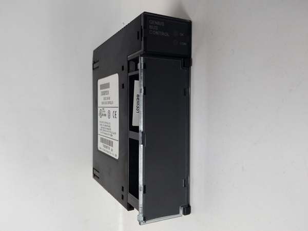
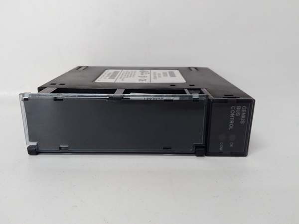
| LED Indicators | OK, COMM OK (2 status LEDs) |
| Compatible PLCs | Series 90-30, Series 90-70, Series 6, Series 5 |
| Required CPU Firmware | Release 5.0 or later (for Series 90-30) |
| Supported Devices | Genius Blocks, Remote Drops, Field Control Stations, HHM |
| IP Rating | IP20 |
| Operating Temperature | 0°C to 60°C (32°F to 140°F) |
| Storage Temperature | -40°C to 85°C (-40°F to 185°F) |
| Humidity (Non-condensing) | 5% to 90% |
| Mounting Style | Backplane or Panel Mount |
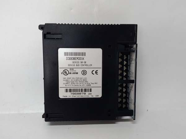
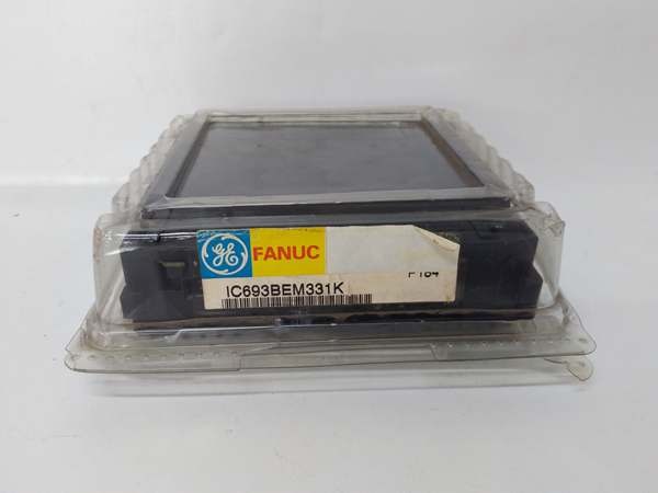
GE IC693BEM331
4. Product Introduction
The GE IC693BEM331L represents Revision L of the Series 90-30 Genius Bus Controller, serving as the interface between the PLC and the proprietary Genius I/O serial bus. It enables high-speed data exchange with up to 31 distributed field devices, including Genius blocks, remote I/O drops, and Field Control stations, handling up to 128 bytes of input and output data per scan.
The technical advantage lies in its versatile integration capabilities—supporting discrete, analog, and specialized field devices while maintaining robust communication via Global Data and datagrams. The module draws less than 300mA from the backplane, eliminating the need for external power, and features built-in diagnostics via two front-panel LEDs for rapid fault identification in distributed control architectures, with Revision L incorporating specific firmware and component updates.
5. QA & Testing SOP (Transparency Building)
1. Incoming InspectionEvery incoming unit undergoes traceability verification. We validate the part number and confirm Revision L on the label against the GE Fanuc/Emerson datasheet, checking for physical damage, bent connector pins, or counterfeit indicators. Anti-counterfeit verification includes weighing the module (410g spec) and inspecting PCB component markings against known originals to ensure authenticity.
2. Live TestingWe bench-test the module in a live Series 90-30 chassis configuration. This involves powering the backplane, verifying both status LEDs (OK and COMM OK) illuminate correctly during power-up diagnostics, and executing a 24-hour burn-in test. We verify active communication with a known-good Genius I/O block or Hand-Held Monitor to confirm data transmission integrity at Revision L compatibility levels.
3. Electrical TestingUsing a Fluke 1587 Insulation Multimeter, we measure isolation resistance between the backplane and communication circuits, ensuring it exceeds 10MΩ. We validate that the 5VDC current draw remains under the 300mA specification under full load and verify ground continuity from the mounting bracket to the backplane reference.
4. Configuration & Firmware CheckWe connect a Genius Hand-Held Monitor to read the firmware version and internal configuration settings. For refurbished units, we ensure the module can be successfully configured to communicate at various baud rates (153.6 kbps standard) and verify that the Device Present bit functions correctly across all 31 configurable addresses with Revision L firmware.
5. Final QC & PackagingEach module receives a QC tag documenting test results, current draw readings, and firmware version. We wrap the unit in anti-static bubble wrap and place it in a conductive static-shielding bag. The outer box includes desiccant packs to prevent moisture ingress during transit.

GE IC693BEM331
6. Installation Pitfalls & Guide (Engineer to Engineer)
❗ Firmware Version IncompatibilityThe IC693BEM331L requires Series 90-30 CPU firmware Release 5.0 or later to operate correctly. Attempting to install Revision L on an older CPU (e.g., pre-5.0 firmware) will result in communication failures or the CPU failing to recognize the hardware. Verify CPU firmware revision via Logicmaster 90 or Proficy Machine Edition before installation—Revision L may have specific minimum firmware requirements.
❗ Incorrect Bus TerminationThe Genius Bus requires proper termination at both ends of the trunk cable. Failing to install the 120Ω termination resistors (often built into the end device) or installing them at incorrect locations will cause signal reflections and complete communication loss. Always verify impedance measurements at the bus endpoints with a multimeter.
❗ Data Length Configuration ErrorsThis module does not count fault-table configuration errors like the Series 90-70 GBC. If you configure I/O data lengths that do not match the actual field device (e.g., setting 16 bytes for a block sending 8 bytes), the “OK” LED will blink, and communication will fail. Always verify the Device Present bit is set to 1 in the configuration software after setup.
❗ Backplane Power HeadroomWhile this unit draws less than 300mA, racks populated with multiple communication modules or high-current analog cards can exceed the power supply’s capacity. Calculate total 5VDC load. Exceeding the PWR330/PWR321 rating will cause intermittent bus failures or random PLC resets during scan cycles.
❗ ESD Damage During SwapI’ve seen technicians destroy these modules by handling them without grounding. The communication circuits are ESD-sensitive. Always power down the chassis, wear a grounded wrist strap, and touch the chassis ground plane before removing or inserting the module. Static discharge can corrupt the bus controller logic instantly.
Replacement Guide
- Pre-install: Document current Genius Bus addresses and data length configurations for all 31 devices. Record the firmware version from the old module using the Hand-Held Monitor.
- Removal: Power down the chassis. Disconnect the Genius trunk cable from Serial 1 and Serial 2 terminals. Remove the mounting screws and extract the old module carefully.
- Install: Insert the new unit into the backplane, ensuring the connector engages fully. Reconnect the Genius trunk cable (Serial 1 to Serial 1, Serial 2 to Serial 2, Shield to Terminal 16). Secure mounting screws.
- Power-on Test: Power up the chassis. Verify the “OK” LED illuminates steady. Enter Run mode and confirm the “COMM OK” LED lights steady. Use the Hand-Hold Monitor to verify all 31 devices show “Present” status with Revision L firmware.
7. FAQ (Frequently Asked Questions)
Q: Is this module hot-swappable?A: No. The IC693BEM331L is not hot-swappable. Removing it while the chassis is powered draws current from the live backplane, risking damage to the module and backplane connector. Always de-energize the PLC rack before installation or removal.
Q: What does the “-L” suffix indicate?A: The “-L” suffix denotes Revision L of the hardware. This revision includes specific component changes and firmware compatibility updates from earlier revisions. Always match the revision to your system’s compatibility requirements unless an upgrade path is documented. Revision L is functionally identical to other revisions in terms of I/O capacity and protocol.
Q: Can I use this controller with RX3i systems?A: Yes. The IC693BEM331L is functionally identical to the IC694BEM331 (RX3i version). You can install a Series 90-30 module in an RX3i rack. However, in configuration software, you must select the module type matching your rack—select IC693BEM331 for 90-30 systems and IC694BEM331 for RX3i systems, though the hardware is interchangeable.
Q: What is the difference between a Bus Controller and a Genius Communications Module (GCM)?A: They serve different purposes. The Bus Controller (IC693BEM331L) manages I/O data exchange with Genius blocks and remote drops. The GCM/GCM+ modules handle enhanced peer-to-peer communications and global data sharing. Genius blocks cannot be controlled by GCM modules—they require the Bus Controller.
Q: Why does my OK LED blink instead of staying solid?A: A blinking OK LED indicates a configuration mismatch, not a hardware fault. This typically occurs when the configured I/O data length in the GBC does not match the actual data length provided by a Genius block or remote drop (e.g., non-byte-aligned data). Re-verify the data length configuration in Proficy Machine Edition.
Q: What warranty options exist for discontinued units?A: Since this is discontinued by Emerson, warranty depends on the supplier. Reputable vendors typically offer a 1-2 year warranty on remanufactured units covering board-level failures. Always request documentation of the testing procedure and warranty terms before purchasing.
Q: Does this module support Phase A Genius Blocks?A: No. The IC693BEM331L is incompatible with older Phase A Genius Blocks. It is designed to work with Phase B and later Genius I/O blocks, Remote Drops using Series 90-70 I/O modules, and Field Control I/O stations.


