
Description
3. Key Technical Specifications
| Parameter | Value | |
|---|---|---|
| Number of Controlled Axes | 1 (Single Axis) | |
| Servo Loop Update Rate | 1 millisecond | |
| Operating Modes | Standard Mode; Follower Mode (Electronic Gearing) | |
| Position Feedback | Incremental encoder input (A, B, Z phases) | |
| Command Interface | ±10V analog velocity command | |
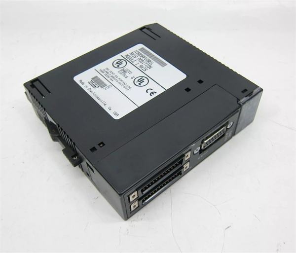
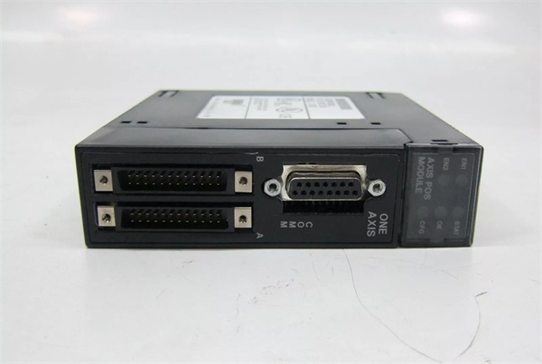
| Axis Connector | 25-pin D-shell connector (Type D) | |
| Maximum Modules per System | 3 (CPU 311/313/323) | 8 (CPU 331+) |
| Supported Cables | IC693CBL311/319/317/320 | |
| Power Consumption | 5VDC from backplane | |
| LED Indicators | EN1, EN2, STST, OK, CFG | |
| Operating Temperature | 0°C to +60°C |
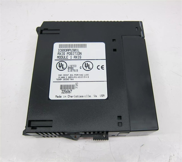
GE IC693APU301
4. Product Introduction
The device is a single-axis positioning module designed for Series 90-30 PLC systems, enabling precise control of servo motors through both standard and electronic gearing follower modes. It integrates motion control with PLC logic, eliminating the need for a separate motion controller.
The unit provides 1ms servo loop update, ensuring high-performance closed-loop control with minimal following error. Its dual-mode capability supports both standalone positioning tasks and synchronized master-slave applications like conveyor tracking or web handling.
5. QA & Testing SOP
1. Incoming Inspection
- Verify part number and revision letter against OEM records. Use high-resolution imaging to authenticate GE logo and serial number hologram.
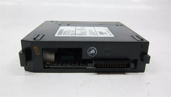
- Check 25-pin D-shell and 24-pin high-density connectors for bent pins or corrosion. Confirm all 5 LED indicators (EN1, EN2, STST, OK, CFG) are present.
2. Live Testing
- Mount in Series 90-30 test rack with CPU331 and GE IC693PWR321 power supply. Power on and confirm OK and CFG LEDs illuminate.
- Configure using VersaPro v1.1+ software. Upload 5 basic motion programs and execute continuous motion cycles for 24-hour burn-in.
- Use Fluke 115 multimeter to verify ±10V velocity command output range and encoder signal integrity with a 2000PPR test encoder.
3. Electrical Testing
- Measure isolation resistance between field terminals and backplane with Megger insulation tester: must exceed 10MΩ @ 500VDC.
- Test ground continuity using Fluke 115 multimeter. Verify star grounding configuration with <0.5Ω resistance between all connected components.
4. Firmware/Config Backup
- Record firmware version via Logic Developer-PLC. Capture photo of module serial number and configuration parameters.
- Save motion programs and parameter settings to backup USB drive. Document maximum module limits for different CPU models.
5. Final QC & Packaging
- Affix calibration tag with measured velocity command accuracy (±0.2% full scale). Package in anti-static bag with terminal block protector.
- Include required cables (IC693CBL311 or equivalent) and configuration documentation. Label with OEM part number and “New Surplus” status.

GE IC693APU301
6. Installation Pitfalls & Guide
❗ CPU Compatibility OversightMismatched CPU models cause hard-to-diagnose communication failures. CPU311/313/323 support max 3 modules, while CPU331+ support up to 8. Calculate total modules across all racks before installation. Failure to follow this limit results in unrecognized modules or data corruption.
❗ Software Version IncompatibilityOlder VersaPro versions (pre-v1.1) cannot properly configure the device. This causes incomplete parameter uploads and potential servo faults during operation. Verify software version using Help > About before attempting configuration.
❗ Cable Selection for Noise ImmunityUsing non-GE-specified cables in high-noise environments causes encoder signal dropout. The 8″ external shield pigtail on IC693CBL317/320 must be grounded within 6 inches of the module to maintain >70dB common mode rejection.
❗ Grounding Configuration ErrorsImproper star grounding creates ground loops and servo instability. The unit, servo drive, and encoder must share a single common ground point with <0.5Ω resistance between all devices. Never daisy-chain ground connections between components.
4-Step Replacement Guide
- Pre-Install: Record existing configuration parameters and motion programs. Verify CPU model and calculate total module count. Order required GE-specified cables if needed.
- Removal: Power off entire rack. Label all wiring with corresponding terminal numbers. Disconnect servo drive and encoder cables. Remove mounting screw and extract module from slot.
- Install: Align module with slot guide rails and push firmly until seated. Secure with mounting screw. Reconnect all wiring using labeled terminal map.
- Power-on Test: Power on rack and verify OK/CFG LEDs illuminate solid. Upload saved configuration and test motion sequences at 50% speed. Monitor following error using Logic Developer-PLC diagnostic tools.
7. FAQ
Q: Can this module be used with stepper motors?A: No, the unit is optimized for closed-loop servo applications with encoder feedback. While it accepts ±10V velocity commands, it lacks stall detection and current limiting required for stepper motor control.
Q: Is hot-swapping supported?A: No. The device must be installed/removed with system power off. Hot-swapping risks backplane bus damage and corrupts shared memory data. Always follow lockout/tagout procedures during replacement.
Q: What is the warranty policy for new surplus units?A: Our new surplus inventory includes a 12-month replacement warranty. This does not cover damage from improper installation, ESD events, or use with unsupported hardware/software.
Q: Can firmware be updated in the field?A: No, the unit does not support field firmware upgrades. Configuration parameters can be modified via software, but base firmware is factory-programmed and non-upgradable.
Q: What are the best practices for commissioning follower mode?A: 1. Start with 1:1 gear ratio at low speed. 2. Verify master encoder signal integrity with oscilloscope. 3. Set following error limit to <0.5% of travel. 4. Test emergency stop response to ensure synchronized halting.


