
Description
Hard-Numbers: Technical Specifications
- Input Channels: 12 positive-logic source inputs
- Output Channels: 4 positive-logic outputs
- Input Voltage: 5 VDC only (TTL compatible)
- Output Ratings: 10-30 VDC @ 500 mA maximum, or 4.75-6.0 VDC @ 20 mA maximum
- Maximum Count Rate: 80 kHz (High Frequency mode), 20 Hz (Low Frequency mode)
- Counter Modes: Up, Down, Bidirectional (Quadrature), Difference between two values
- Counter Configuration: 4 identical independent simple counters, 1 complex counter, or 2 identical independent complex counters
- Input Filter (Selectable): High Frequency – 2.5 µs; Low Frequency – 12.5 ms
- Selectable On/Off Output Presets: Each counter has 2 preset points (On and Off)
- Counters Per Timebase: Each counter stores counts in configurable timebase (1 ms to 65535 ms)
- Strobe Register: Each counter has strobe registers capturing accumulator value on strobe input transition
- Counter Operation Types: Type A (Up or Down – 4 counters), Type B (Both Directions – Quadrature – 2 counters), Type C (Difference between 2 values – 1 counter)
- Output Protection: 3 Amp fuse for all output points
- Power Consumption: 250 mA @ 5 VDC from backplane
- Isolation: 250 VAC continuous between field and backplane
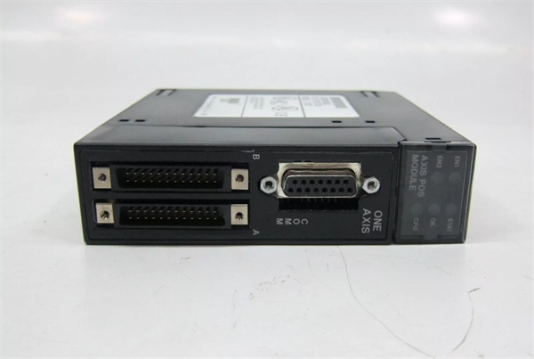
- LED Indicators: BOARD OK (green), CONFIG OK (green)
- Operating Temperature: 0°C to +60°C (32°F to 140°F)
- Storage Temperature: -40°C to +85°C (-40°F to +185°F)
- Lifecycle Status: Discontinued/Obsolete

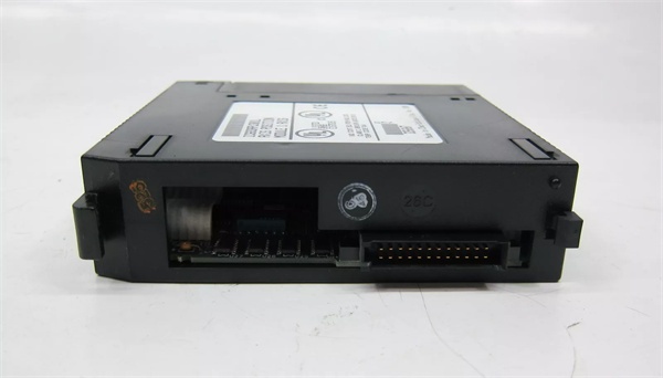
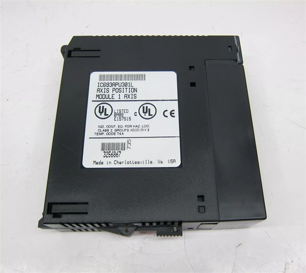
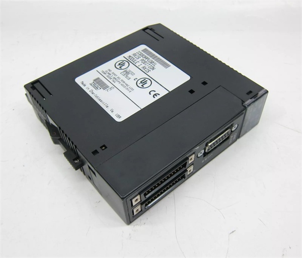
GE IC693APU301
The Real-World Problem It Solves
Standard PLC digital inputs can’t handle high-speed TTL-level pulse signals from optical encoders and flow sensors. The IC693APU301 provides dedicated 5 VDC input buffers that process pulses up to 80 kHz independently of the PLC scan cycle, ensuring accurate counting of low-voltage, high-frequency signals that would overwhelm standard I/O.
Where you’ll typically find it:
- Optical encoders: TTL-level quadrature encoders for precision position feedback in servos and indexing tables
- Optical sensors: High-speed photodetector and proximity sensor pulse counting in packaging and sorting applications
- Turbine flowmeters: Low-voltage pulse output flowmeters requiring TTL-compatible counting
- Material handling: Rapid part counting and length measurement using optical interrupter sensors
Bottom line: The IC693APU301 handles high-speed TTL-level pulse counting at 5 VDC, which standard 24 VDC PLC inputs can’t interface with directly—eliminating the need for external signal conditioning and ensuring no missed counts.
Hardware Architecture & Under-the-Hood Logic
The IC693APU301 is functionally similar to the IC693APU300 but with a critical difference: it only accepts 5 VDC input signals. The module uses TTL-compatible input buffers designed specifically for NPN open-collector encoders and optical sensors that output 0-5 VDC logic levels. All other hardware functions—counter engines, output logic, and CPU communication—operate identically to the IC693APU300.
-
Input Conditioning Stage
- Positive-logic TTL input buffers accept 5 VDC signals only (0 V = Low, 5 V = High)
- Selectable input filter: 2.5 µs for high-frequency mode (80 kHz), 12.5 ms for low-frequency mode (20 Hz)
- Schmitt trigger conditioning provides clean digital edges from 5 VDC sources
- Each input configurable as count signal, direction, disable, edge-sensitive strobe, or preload
- Input voltage clamping provides protection against overvoltage
-
Counter Hardware
- Independent hardware counters operate autonomously from PLC scan
- Counter configurations: Type A (4 simple up/down counters), Type B (2 complex bidirectional quadrature counters), Type C (1 difference counter)
- 32-bit counter accumulators with rollover detection flag
- Hardware-based counting eliminates CPU scan delay
-
Counter Modes of Operation
- Up Counter: Counts pulses on increment input
- Down Counter: Counts pulses on decrement input
- Bidirectional (Quadrature): Decodes A/B phase relationship for direction and count—supports 1x, 2x, and 4x resolution
- Difference Mode: Counts difference between two changing values
-
Strobe & Latch Functions
- Each counter has strobe registers capturing accumulator value on strobe input transition
- Windowing feature allows user-defined valid range for strobe recognition
- Latched values accessible to CPU for position capture events
- Counters-per-timebase register stores counts occurring in specified time window
-
Output Control
- Four positive-logic outputs trigger independently of CPU scan
- Configurable preset points (On and Off) for each counter
- Outputs provide up to 500 mA at 10-30 VDC or 20 mA at 4.75-6.0 VDC
- 3 Amp fuse protects all output points
-
Data Exchange with CPU
- Counter values, status bits, and diagnostic data stored in module registers
- CPU reads data via Series 90-30 backplane bus
- Configuration performed via Logicmaster 90-30/20, Hand-Held Programmer, or Logic Developer-PLC
- No real-time CPU intervention required for counting or output triggering

GE IC693APU301
Field Service Pitfalls: What Rookies Get Wrong
Applying 24 VDC to 5 VDC inputs
Rookies wire a 24 VDC proximity sensor directly to the IC693APU301 input. The input buffer is destroyed, and the module reads permanently high—requiring expensive module replacement.
- Field Rule: IC693APU301 only accepts 5 VDC inputs. Verify sensor output voltage with a multimeter before connecting. For 24 VDC sensors, use an external signal conditioner or step-down module, or switch to the IC693APU300 which accepts 10-30 VDC signals.
Using sinking (PNP) encoders
Rookies connect a PNP sourcing encoder output to the module. The NPN open-collector input expects current sinking, and the signal never pulls low, so the counter never increments.
- Field Rule: IC693APU301 inputs are positive-logic expecting 0-5 VDC TTL signals. Use NPN open-collector encoders (sinking) that pull the line to ground for logic low and leave it floating (weak pull-up to 5 VDC) for logic high. PNP encoders output 24 VDC high and will not work.
Running long 5 VDC encoder cables
Rookies run 100-foot encoder cables from the cabinet to a remote encoder. The voltage drop across the long cable causes signal degradation, and the counter misses pulses at high speeds.
- Field Rule: Keep 5 VDC encoder cables under 50 feet. For longer runs, install the encoder signal conditioning near the sensor, use line drivers for differential signals, or use the IC693APU300 with 10-30 VDC line driver encoders instead.
Not providing pull-up resistors for open-collector outputs
Rookies connect an NPN encoder without pull-up resistors. When the encoder output is high impedance, the input floats and randomly toggles between high and low.
- Field Rule: IC693APU301 has internal pull-up to 5 VDC on inputs. However, if your cable capacitance is high (>100 pF), external 4.7 kΩ pull-up resistors near the module terminals ensure clean high-level signals. Verify with an oscilloscope that idle inputs read 5 VDC.
Mixing APU300 and APU301 configurations
Rookies swap an IC693APU300 for an IC693APU301 in an existing system without changing the configuration. The 5 VDC inputs don’t recognize the 24 VDC encoder signals, and the system fails to count.
- Field Rule: APU300 and APU301 are not drop-in replacements. APU300 accepts 5 VDC or 10-30 VDC; APU301 only accepts 5 VDC. When replacing, verify the module model and input voltage requirements before wiring. Update PLC configuration if changing module types.
Ignoring ground potential differences
Rookies ground the 5 VDC encoder supply to the machine frame ground. Ground potential differences between the PLC cabinet and remote encoder cause false counts and erratic behavior.
- Field Rule: Maintain a common signal ground between the IC693APU301 and the encoder. Connect encoder 0 V to module input common. Do not ground encoder 0 V to earth ground at multiple points—creates ground loops that induce noise on 5 VDC signals.
Forgetting to disable unused inputs
Rookies leave unused counter inputs unconnected. Floating inputs pick up electrical noise, causing phantom counts and false triggers, especially in high-electrical-noise environments.
- Field Rule: Tie unused input terminals to the common (0 V) terminal. This pulls them to a defined logic low state and prevents floating inputs from counting garbage. If floating inputs cause issues, try tying them to 5 VDC instead.
Not verifying TTL signal levels
Rookies assume any encoder will work. Some encoders output 3.3 VDC logic levels, which may not reliably trigger the 5 VDC input threshold, causing intermittent counting.
- Field Rule: Verify encoder output logic high voltage is at least 2.4 VDC (TTL spec). For 3.3 VDC logic levels, use a level shifter or buffer to boost to 5 VDC levels. The IC693APU301 expects standard TTL: 0-0.8 VDC = Low, 2.0-5.0 VDC = High.
Commercial Availability & Pricing Note
Please note: The listed price is for reference only and is not binding. Final pricing and terms are subject to negotiation based on current market conditions and availability.


