
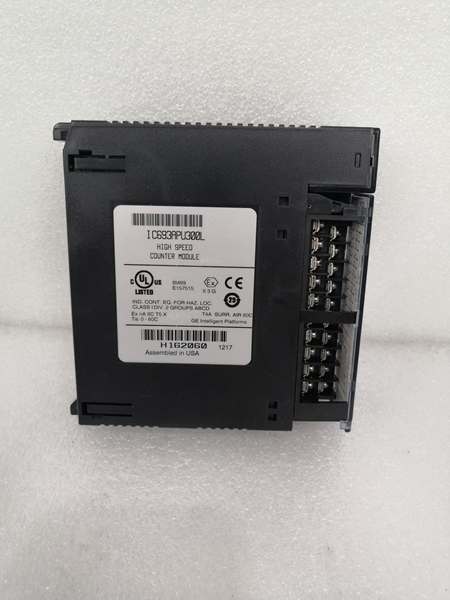
Description
Hard-Numbers: Technical Specifications
- Input Channels: 12 positive-logic source inputs
- Output Channels: 4 positive-logic outputs
- Maximum Count Rate: 80 kHz (High Frequency mode), 20 Hz (Low Frequency mode)
- Input Signal Voltage: 5 VDC or 10-30 VDC (selectable)
- Output Ratings: 10-30 VDC @ 500 mA maximum, or 4.75-6.0 VDC @ 20 mA maximum
- Counter Modes: Up, Down, Bidirectional (Quadrature), Difference between two values
- Counter Configuration: 4 identical independent simple counters, 1 complex counter, or 2 identical independent complex counters
- Input Filter (Selectable): High Frequency – 2.5 µs; Low Frequency – 12.5 ms
- Selectable On/Off Output Presets: Each counter has 2 preset points (On and Off)
- Counters Per Timebase: Each counter stores counts in configurable timebase (1 ms to 65535 ms)
- Strobe Register: Each counter has strobe registers capturing accumulator value on strobe input transition
- Counter Operation Types: Type A (Up or Down – 4 counters), Type B (Both Directions – Quadrature – 2 counters), Type C (Difference between 2 values – 1 counter)
- Output Protection: 3 Amp fuse for all points
- Power Consumption: 250 mA @ 5 VDC from backplane
- Isolation: 250 VAC
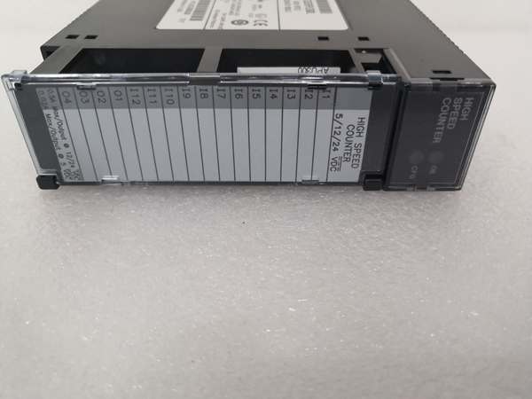
- LED Indicators: BOARD OK and CONFIG OK
- Operating Temperature: 0°C to +60°C (32°F to 140°F)
- Lifecycle Status: Discontinued/Obsolete

IC693APU300
The Real-World Problem It Solves
Standard PLC digital inputs scan every 10-20 milliseconds, which is useless for high-speed encoders and flowmeters generating thousands of pulses per second. The IC693APU300 processes pulse signals up to 80 kHz independently of the PLC scan cycle, counting inputs and triggering outputs without CPU communication—ensuring accurate position tracking and material counting at speeds that would overwhelm standard I/O.
Where you’ll typically find it:
- Turbine flowmeters: Totalizing flow pulses from high-speed turbine meters in custody transfer and process metering applications
- Material handling: Rapid product counting and sorting on conveyor lines running at high throughput rates
- Motion control: Quadrature encoder feedback for servos and AC drives in positioning and velocity control applications
- Velocity measurement: Magnetic pickup pulse counting for tachometers and speed monitoring
Bottom line: The IC693APU300 handles pulse counting at rates that standard PLC inputs can’t touch—offload high-speed counting tasks from the CPU and ensuring no missed pulses.
Hardware Architecture & Under-the-Hood Logic
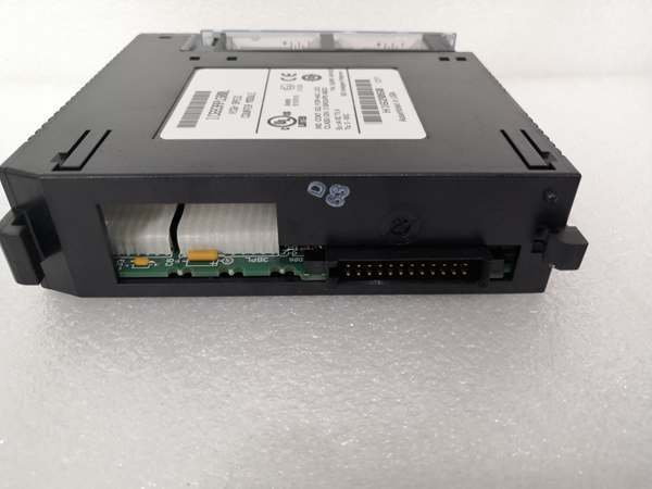
The IC693APU300 is a single-slot high-speed counter module that operates independently of the PLC scan cycle. It uses hardware-based counters that process pulse signals directly from the input circuitry, with no CPU intervention required for counting or output triggering. The module communicates with the CPU via the backplane for configuration and data retrieval, but all real-time counting happens on-module.
-
Input Conditioning Stage
- Positive-logic input buffers accept 5 VDC or 10-30 VDC signals
- Selectable input filter: 2.5 µs for high-frequency mode (80 kHz), 12.5 ms for low-frequency mode (20 Hz)
- Schmitt trigger conditioning provides clean digital edges
- Each input configurable as count signal, direction, disable, edge-sensitive strobe, or preload
-
Counter Hardware
- Independent hardware counters operate autonomously from PLC scan
- Counter configurations: Type A (4 simple up/down counters), Type B (2 complex bidirectional quadrature counters), Type C (1 difference counter)
- 32-bit counter accumulators with rollover detection flag
- Z input events supported for index/home position detection in Enhanced mode
-
Counter Modes of Operation
- Up Counter: Counts pulses on increment input
- Down Counter: Counts pulses on decrement input
- Bidirectional (Quadrature): Decodes A/B phase relationship for direction and count—supports 1x, 2x, and 4x resolution
- Difference Mode: Counts difference between two changing values
-
Strobe & Latch Functions
- Each counter has strobe registers capturing accumulator value on strobe input transition
- Windowing feature allows user-defined valid range for strobe recognition
- Latched values accessible to CPU for position capture events
- Counters-per-timebase register stores counts occurring in specified time window
-
Output Control
- Four positive-logic outputs trigger independently of CPU scan
- Configurable preset points (On and Off) for each counter
- Outputs can source up to 500 mA at 10-30 VDC or 20 mA at 4.75-6.0 VDC
- 3 Amp fuse protects all output points
-
Data Exchange with CPU
- Counter values, status bits, and diagnostic data stored in module registers
- CPU reads data via Series 90-30 backplane bus
- Configuration performed via Logicmaster 90-30/20, Hand-Held Programmer, or Logic Developer-PLC
- No real-time CPU intervention required for counting or output triggering

IC693APU300
Field Service Pitfalls: What Rookies Get Wrong
Running encoder cables near VFD outputs
Rookies route encoder cables in the same conduit as VFD motor leads. The induced noise causes false counting at 80 kHz, and the material handling system counts phantom products, triggering false alarms and inventory discrepancies.
- Field Rule: Keep encoder cables at least 12 inches away from VFD motor leads. Use shielded twisted-pair encoder cable with foil + braid shield. Ground the shield at the module end only—never ground both ends. For 80 kHz signals, even small amounts of noise cause false counts.
Selecting the wrong input filter for pulse rate
Rookies configure the 12.5 ms input filter for a 50 kHz pulse train. The filter averages the signal and the module misses pulses, causing position drift and count errors.
- Field Rule: Match the input filter to your pulse rate. Use the 2.5 µs High Frequency filter for anything above 1 kHz. Only use the 12.5 ms Low Frequency filter for slow signals under 100 Hz. If you’re unsure, start with High Frequency mode and only switch if you see bounce.
Mixing quadrature resolution modes
You replace a failed encoder but don’t verify the quadrature mode in the PLC configuration. The old encoder used 4x mode, the new one uses 1x mode, and the machine now loses 75% of its positioning resolution.
- Field Rule: When replacing an encoder, verify the quadrature resolution setting (Type B mode configuration) matches the encoder specification. A 1000 PPR encoder in 4x mode counts 4000 pulses per revolution—in 1x mode it’s only 1000. The difference at 80 kHz counting speed is massive.
Forgetting to configure counter type
Rookies install the module and leave it in default Type A configuration (4 simple counters) when they actually need Type B (bidirectional quadrature). The encoder pulses feed a simple up counter and direction changes are ignored—the machine hunts back and forth around the setpoint.
- Field Rule: Verify counter type configuration before commissioning. Type A for simple up/down counting, Type B for quadrature encoders, Type C for difference counting. If you’re using an A/B encoder, you must configure Type B bidirectional mode.
Exceeding output drive current limits
Rookies try to drive a 24 VDC relay coil directly from the module output. The 500 mA rating is exceeded, the output fuse blows, and the module 终止s triggering outputs entirely.
- Field Rule: Check your load current before wiring. Outputs provide 500 mA maximum at 10-30 VDC or 20 mA maximum at 4.75-6.0 VDC. If you need more drive, use an interposing relay or external driver—don’t overload the module outputs directly.
Ignoring the strobe windowing feature
Rookies configure a strobe input but don’t set the valid window range. Noise on the strobe line triggers false captures at random intervals, and the PLC reads latched values that don’t represent true position.
- Field Rule: Always configure the strobe window range for your application. Set minimum and maximum accumulator values where the strobe is recognized as valid. Outside this range, the strobe is ignored—this prevents false captures from noise or out-of-range conditions.
Leaving unused inputs unconnected
Rookies leave unused counter inputs disconnected. The floating inputs pick up electrical noise, causing the counter to drift randomly and triggering false position or count alarms.
- Field Rule: Short unused inputs together at the terminal block. Connect the positive terminals of unused inputs to each other to tie them to a defined logic state and prevent floating inputs from counting garbage.
Not verifying direction before commissioning
Rookies wire an encoder and power up the high-speed machine without checking direction. The machine drives backward when commanded forward, crashing into hard 终止s and damaging equipment.
- Field Rule: After wiring, jog the axis slowly in the forward direction and verify the counter is incrementing (not decrementing). If backward, swap the A and B channels or change the direction bit in the configuration—never swap the motor leads to compensate.
Commercial Availability & Pricing Note
Please note: The listed price is for reference only and is not binding. Final pricing and terms are subject to negotiation based on current market conditions and availability.


